Frequently Asked Questions
Below you will find many of the commonly asked questions our technical support staff receive on a daily basis. Use this material as a guideline to diagnose your vehicle's electrical situation.
This information is believed to be accurate and reliable, however, we are not liable for its content. By using the information herein, you certify that use of the following information is at your own risk and that you accept all responsibility and liability, without limitation, of any occurrence of damage to person or property as a result of using the information. This information can not be copied or duplicated in any way.
If you see a discrepancy with any information shown, please let us know.
About Our Products and things to know before placing an order.
Believe it or not, your car's original wiring harness had a service life of only 10 years! For you folks with car's from the 50's, with original harnesses, you have exceeded the service life of your car's wiring by forty years!!!
When we hear people telling us that the wiring in their 1950s or 1960s car is still 'in great shape', we have to shake our heads and disagree. We don't make this statement just because we are in the business of selling wiring harnesses.
It comes down to an issue of deterioration. There is no practical way to completely seal-off the circulation of air and moisture between individual wire strands in a wire. In addition, most automotive wiring is not protected from hydrocarbon contamination.
The majority of automotive wire is made of copper strands. Copper is considered to be an active metal, which means that it readily reacts with oxygen, moisture, and airborne pollutants. If you don't believe that cooper is active, leave a nicely polished copper teakettle in your kitchen for a month or two and watch it lose its shine. The same applies to stranded (automotive grade) copper wire.
Corrosion causes electrical resistance. Electrical resistance causes heat and other electrical anomalies.
If your wire has become brittle and cracked, it is now in the next stage of deterioration. It is in immediate need of replacement. At this stage, a short circuit to ground is eminent. In a worst case scenario, it can cause a fire.
Even if you are one of the few lucky enough to even find an N.O.S. wiring harness, the wire strands will have deteriorated over time just by sitting on a shelf. For this reason, it would not be wise to purchase an N.O.S. harness.
The same corrosion factor happens to the wire's terminals over time.
Lectric Limited offers wiring harnesses with brand new wire. Get rid of your car's electrical problems, or potential problems, by replacing all the wiring with new harnesses from Lectric Limited!
Not all harnesses are manufactured by Lectric Limited. But Lectric Limited is the ONLY manufacturer that circuit tests each harness before it leaves their facility. This is the only way to insure that your harness functions perfectly BEFORE you install.
Many manufacturers will warranty their products. But you don't want to have to tear-out your brand new harness because it was not assembled properly, after you've spent hours on installation...not to mention the potential fire hazard. Why not buy a harness that has been circuit tested before you install it so you only have to install it once?
Yes. We are the manufacturer of all our 1953-82 Corvette, and 1955-57 Chevrolet Full-Size and Jeep wiring products. Additionally, most components in our products are purchased directly from GM's original harness manufacturer or their approved vendors. Our wiring products are sold by many dealers in the automotive restoration market. Watch how they're made on Our YouTube Channel.
Yes. The harness you receive should be ready to fasten-down and connect to your vehicle.
In rare instances, some of the original connectors needed to manufacture a harness may no longer be available to us. In this case, you would need to use an original connector from your old harness. However, in most cases we will include a functional replacement connector on your new harness. It will function correctly, and be electrically sound, by may not be correct if you are concerned with having your car judged.
Also, we recommend that before you install your new harness, you compare it with your original harness to insure you ordered the correct harness for your application.
Absolutely! 99.99% of our reproduction (not replacement) products will pass the rigorous judging standards of ALL the major Corvette and Chevrolet awards - and be 100% accurate!
That being said, if you were to call us to inquire about our products, we would prefer you ask specific questions like, 'Are the colors of the wires in your harness exactly as original?' rather than ask, 'Will this pass NCRS?' or, 'The judge took points off my old harness. Is your harness correct?' When it comes to automotive wiring and electrical, we know what was original, and what wasn't. We have the original blueprints, and it's our BUSINESS to know. People who judge's car shows as a hobby, perhaps once a year, can make mistakes. :-)
Our strive for perfection, accuracy, and attention to detail has kept us in business for over 35 years.
Absolutely! Whether it be for Chevrolet, Buick, Oldsmobile, Pontiac, Cadillac, GMC, Chrysler, or Jeep, 99% of our reproduction (not replacement) products will pass the rigorous judging standards of ALL the major automotive awards - and be 100% accurate!
This strive for perfection, accuracy, and attention to detail has kept us in business for over 30 years.
All of our spark plug wire sets include wire routing instructions.
All of our 'Custom Update Series Wiring Systems' include wiring instructions. Even scripted on the wires themselves are locations to where that circuit goes to (ex. the wires that go to the headlights would have 'headlights' scripted on the wire leads).
A few of our specialized harnesses and kits do include instructions and schematics. These include: 1947-1959 Chevy Truck Complete Wiring Sets, Camaro Console Gauge Conversion Harnesses, GTO Rally Gauge Adapter Harness, Corvette T.I. Ignition Module, all Alternator Conversion Harnesses and a few others.
However, installation instructions, schematics and wiring diagrams are usually not included with our exact reproduction wiring harnesses, nor were they ever included with harnesses once available from dealers or part's store.
We suggest that you have a 'Factory Assembly Manual' on hand when installing your new harness. 'Factory Assembly Manuals' (if available for your year/make/model) contain general overview schematics, as well as line drawings of how to route the harnesses within your car. The Assembly Manual is what the factory assembly line workers used to properly route the wires - so they reach where they are supposed to. These Assembly Manuals are usually available from your restoration part's supplier. (Note: A 'Service' or 'Shop' manual will usually not provide any information on harness routing).
Another installation tip is to install your new harness at the same time you are removing your old harnesses - one step at a time.
FYI: We do sell laminated wiring diagrams for 53-82 Corvettes and some Chevrolet vehicles that are most beneficial when trying to troubleshoot an electrical problem, but are not much use when installing a harness.
Although the N.C.R.S. manuals are very accurate, there are some flaws; specifically in the areas of battery cable part numbers, scripting on spark plug wire, and spark plug wire boot colors.
So, to answer the question, we are correct! 30 years in the business will attest to this fact. This is our business, not our hobby.
Although it is rare, some of our harnesses require that you ship us a 'donor' harness. We will use one or more components off this donor harness to manufacture your new harness.
NOTE: Requiring a donor harness does NOT mean that we can/will make a harness from your sample harness if it is not alrady listed in our catalog.
The reason for requiring components from a donor harness is that some of the unique components required to manufacture a new, reproduction harness, are no longer available, and no longer being reproduced. Without these essential components, your harness can not be produced. (Of course we use all brand new wire and a majority of new terminals and connectors.)
The needed components are usually (but not limited to) connectors. This can include your original fuse block or bulk head connector (the bulk head connector is the one that goes through the firewall). Your donor connector(s) must be good physical condition and not broken. We will carefully remove the component(s) from the donor harness. If a connector is used from your donor harness, we will replace the all the terminal(s) with new ones. If a fuse block is needed, we will replace all the fuse clips with new ones.
When you place an order for a harness that requires a 'donor' harness, we will contact with more specific information, after we receive your order. If your connector, or any other needed component is not useable when we receive it, we will not be able to manufacture your harness.
If you need to send us a needed component(s), if possible, we highly recommend that you send us your entire harness and not cut the components from the harness. There have been instances where the customer damaged these components when they tried to remove them from the harness. Or instances where more components were needed from the original harnesses than initially thought; resulting in multiple shipping charges incurred by the customer.
Harness purchases that require a 'donor' harness include, (but may not be limited to):
- Buick Full-Size Power Window Harness
- Buick Skylark/Special (1964-67) Dash Harness
- Buick Skylark/Special Power Window Harness
- Chevrolet Chevelle/Monte Carlo/El Camino Power Window Harness
- Chevrolet Full-Size (1963) Dash Harness
- Chevrolet Full-Size Power Window Harness
- Oldsmobile Cutlass/F85 (1964-67) Dash Harness
- Oldsmobile Cutlass/F85 Power Window Harness
- Oldsmobile Full-Size (1958) Main Harness
- Pontiac Full-Size (1955-62) Dash Harness
- Pontiac Full-Size (1964-67) Engine Harness
- Pontiac Full-Size (1964-67) Front Light Harness
- Pontiac Full-Size Power Window Harness
- Pontiac GTO/Lemans/Tempest Power Window Harness
These are a 'special order' item. Call us if you have any questions.

If your vehicle's fuse block/fuse panel (usually pre-1959) is made of the reddish-brown/tan fiber board material, then these fuse blocks were not part of your original harness (shown below). Consequently, we do not include them with our dash harness or Custom Design™ truck harness for that vehicle.
However, if your fuse block was of the type made with the black phenolic/bakelite material (shown below), these fuse blocks were originally part of the dash harness. Consequently, we do include them* with our dash harness for that vehicle.
However, if your fuse block was of the type made with the black phenolic/bakelite material (shown below), these fuse blocks were originally part of the dash harness. Consequently, we do include them* with our dash harness for that vehicle. * Exceptions would be when we require a customer's donor harness in order to re-use their original fuse block. This is a rare occurrence and only required when we are not able to obtain a new, reproduction fuse block.
All of our Custom Update™ harnesses come with a fuse block.
No. We do not refurbish old wiring. We only manufacture brand new wiring harnesses.
Also, we do not recommend refurbishing old wiring harnesses as many times the wire and terminals have begun oxidized (leading to high resistance) and the plastic connectors have begun to deteriorate.
Yes! Our Battery Butler® BBFC100 chargers are designed for use on wet-cell, gel-cell or OPTIMA™ batteries. OPTIMA™ Batteries use AGM (Absorption Glass Mat) technology. These batteries can be charged at normal lead-acid regulated charging voltages.
C.A.C. = 'Controlled Air Comfort' manual control, fresh air ventilation.
Cars of this era were either manufactured with:
- A/C (the only factory air-conditioning system available)
- C.A.C. (manual control, fresh air ventilation only)
- C.A.C. A/C (C.A.C. & optional factory air-conditioning)
- Comfortron A/C (optional factory auto temp./climate control air-conditioning)
- CoolPack A/C (optional under dash air-conditioning unit, usually dealer installed)
What Do I Need To Buy?
Our 'What Corvette Harness Goes Where?'' chart will help you determine the specific harness you might need to correct an electrical problem in your 1953-67 Corvette.
Many times, customers call us to ask, 'What is the harness I need to buy that goes from 'here' to 'there'?'
This chart should help you determine the specific harness, harnesses, or lead wires you might need to either re-wire an entire area of your Corvette (ex. the entire under-hood wiring), or to re-wire a specific component (ex. the starter motor).
As you will see, some harnesses route to different sections of the car (ex. the dash harness runs from the passenger compartment into the under-hood area; wiring components within both those areas).
Currently, this chart only goes up to 1967 Corvette. We are working on updating it to include later year Corvettes.
(also see answer below)
As a general rule:
The Engine Harness runs along the upper part of the firewall (below the windshield).
The Forward Lamp Harness runs along the driver's side fender.
First, identify the wiring that goes to the generator/alternator and trace it back. If the generator/alternator wiring connects to the harness that runs along the firewall (under the windshield), then you will need the Engine Harness. If the alternator wiring connects to the harness that runs along the driver's side fender, then you need the Forward Lamp Harness.
For Corvettes:
- From 1953-57 the charging system wiring of a Corvette was incorporated into the Dash Harness.
- From 1958-62 the charging system wiring of a Corvette was incorporated into the Dash Harness, Engine Harness, and Regulator to Generator Harness.
- From 1963-67 the charging system wiring of a Corvette was incorporated into the Engine Harness.
- From 1968 & up, the charging system wiring was incorporated into the Forward Lamp Harness. Keep this in mind when ordering a harness to correct a charging problem.
(also see answer above)

Using the correct terminology makes a big difference when talking to someone about your car's electrical system. Whenever discussing your vehicle's electrical needs, please take into consideration what you're talking about. The TERMINAL is the metal piece (usually brass or copper) that gets crimped to the wire(s). The CONNECTOR is the piece that the terminal plugs in to (usually plastic).
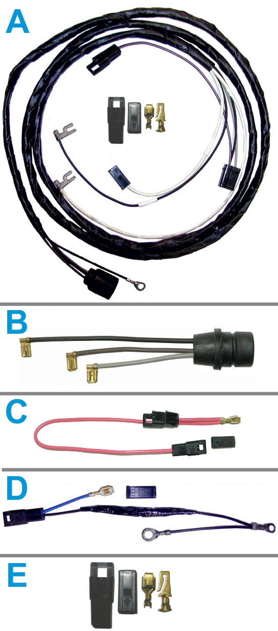
If you want to replace all the wiring for your 1964-71 Corvette's T.I. (transistorized ignition), you will need to buy:
- A) Auxiliary Harness,
- B) Amplifier Box Extension,
- C) Extension Wire (1968-71 Corvettes),
- D) Voltage Regulator Adapter Harness (1965 Corvettes).
Below is a brief explanation of these components.
A) T.I. AUXILIARY HARNESS
This is the main wiring that goes from the distributor to the T.I. amplifier box. On Corvettes, this harness mates to the wires coming from the rubber molded connector (or from the rubber molded pigtail) coming from the T.I. Amplifier Box.
This T.I. Auxiliary Harness includes the resistance wire and the conversion kit. The conversion kit is necessary to convert one of our new engine harnesses to accept this T.I. harness. If your car already has an engine harness that was factory-converted to accept the T.I. harness, and your harness has not been modified or repaired since, then you won't need to use the conversion kit. The conversion kit can be discarded or saved for possible future use. (It is up to you, or your mechanic, to determine if your harness has been previously modified or repaired.)
B) T.I. AMPLIFIER BOX EXTENSION
This is the wiring from the internal circuit board that includes the rubber molded T.I. Amplifier Box housing connector -to- the T.I. Auxiliary Harnesses molded rubber connector. Basically, it is the wiring that is part of the amplifier box. This is the weakest link in the T.I. system and must be replaced if you have not already done so. Over the years, the spring-tension on the female terminals of this wiring WILL lose their 'grip' on the male terminals they connect to, causing your engine to quit.
C) T.I. EXTENSION WIRE
Used only on 1968-71 Corvettes, this is the wire that goes from the ignition switch, through the firewall, to the T.I. Auxiliary Harness.
D) T.I. VOLTAGE REGULATOR ADAPTER HARNESS
Used on 1965 Corvettes only, this harness is used to filter-out ignition noise caused from the engine harness. Without this Adapter Harness, noise induced into the T.I. harness from the Engine Harness could cause your engine to mis-fire. This harness contains a noise canceling diode. The actual application of this harness is vague. No documentation is available as to whether it's used on a big block, small block or both. However, we do sell this harness (# V VR6500A).
E) T.I. CONVERSION KIT
We offer this conversion kit because some dealers do not include this kit as part of the T.I. Auxiliary Harness (We do!). This kit includes all terminals, connectors & instructions as used by the factory to install T.I. This kit is not necessary if your 1964-71 Engine Harness and 1964-67 Dash Harness have already been converted to accept T.I. This kit is also not necessary if you purchase a Lectric Limited T.I. Auxiliary Harness directly from us, since we include the conversion kit.
For your convenience, we are providing copies of our T.I. Conversion Kit Instructions Sheets. Click for:
- 1964-65 Corvette (part # VTR6465CK)
- 1966-67 Corvette (part # VTR6667CK)
- 1968-71 Corvette (part # VTR6871CK)
Other T.I. items we carry:
T.I. AMPLIFIER BOX MODULE
This is a solid-state T.I. module that replaces the original circuit board. It fits completely inside your amplifier box making it undistinguishable from original. It is a simple screw-in replacement. We offer this module for 1964-71 Corvettes.
Did you know that many times a problem with an original T.I. system can be traced back to the electronic components. Many years ago, when the T.I. system was developed, Germanium transistors were 'state-of-the-art' in electronic technology. This type of transistor, however, had many limitations and many amplifier failures can be traced back to these transistors. Our VTR6571AM replacement module uses the newer type Silicone transistors that rarely fail. Other problems that led to amplifier failure were due to water from a faulty cover seal. Moisture trapped inside the amplifier box will cause corrosion to the extent it will rust electrical component leads and destroy copper tracks (traces) on the printed circuit board, thus leading to failure. All of the electronic components in our module is completely encapsulated/sealed. If water does get trapped inside your box, the module will not be effected.
NOTE: Transistorized ignition is a very specialized performance option that works well, when it works. When it doesn't, it can be very frustrating. From an originality standpoint, if your car was originally equipped with T.I., you would want to retain the T.I. system.
If you are thinking of converting your car from OEM standard (non-electronic) ignition to T.I., don't do it! Use our Breakerless-SE Electronic Ignition Conversion Kit (#38131) instead. The Breakerless SE will be a cheaper, much easier to install, much more reliable, and better alternative to T.I.
The problem when converting from an externally to an internally regulated alternator is adapting your original harness. Not only do you need to make sure the alternator will still charge the battery, but you'll want to make sure your gauge or warning light is still able to alert you when the system is not charging.
Our recommendation on internally regulated alternators is to use a genuine Delco SI or CS type for all applications.
Lectric Limited offers an easy and inexpensive solution if you want to convert your wiring from an externally regulated alternator to an SI or CS type, internally regulated alternator. Order our Alternator Conversion Harness. View Catalog to see if this harness is available for your vehicle.
F.A.Q. on Internally Regulated Alternators:
The most common alternator ever produced is the 10SI ('SYSTEM INTEGRATED'), with the 12SI being an upgraded version by means of better cooling (noted by a plastic fan) to handle higher current outputs. The 15SI and 17SI are physically larger units.
Delco 10SI Series , 61 Amp, 12 Volt, CW, 1-Groove Pulley
Used On: (1985-73) Buick, Cadillac, Chevrolet, GMC, Olds., Pontiac 4, 6, 8 Cyl. Replaces: Delco 1105360
Delco 12SI Series , 78 Amp, 12 Volt, CW, 1-Groove Pulley
Used On: 1989-83 Buick, Cadillac, Chevrolet, GMC, Olds., Pontiac 4, 6, 8 Cyl. Replaces: Delco 1100250, 1105370, 1105372 & others
Delco 12SI Series, 94 Amp, 12 Volt, CW, 1-Groove Pulley
Used On: (1987-84) Buick, Cadillac, Chevrolet, GMC, Olds., Pontiac 4, 6, 8 Cyl. Replaces: Delco 1101308
The latest series of alternators to be introduced is the CS ('CHARGING SYSTEM') 130 or 144 (for 130mm or 144mm stator).
Delco CS130 Series, 100-105 Amp, 12 Volt, CW, 1-Groove Pulley Used On:
- (1990-88) Buick Estate Wagon 5.0L
- (1990-88) Cadillac Fleetwood Brougham (RWD) 5.0L
- (1990-88) Chevrolet Caprice 5.0L
- (1990-88) Oldsmobile Custom Cruiser 5.0L
- (1989-88) Pontiac Safari Wagon 5.0L
- Replaces: Delco 1101229, 1101275, 1101292
Delco CS144 Series, 140 Amp, 12 Volt, CW, 6-Groove Pulley
Used On:
- (1996-94) Buick Roadmaster 5.7L
- (1996-93) Cadillac Fleetwood Brougham (RWD) 5.7L
- (1996-93) Chevrolet Caprice 4.3L, 5.7L
- (1996-95) Chevrolet Impala 5.7L
- (1995-92) Chevrolet Lumina APV Van 3.8L
- (1995-92) Oldsmobile Silhouette 3.8L
- (1995-92) Pontiac Trans Sport 3.8L
- Replaces: Delco 10479891, 10480201
All 1963 Corvette headlight buckets were originally made of fiberglass. So, our headlight bucket extension harness, designed for use with fiberglass headlight buckets (part # VHX6300), is correct.
However, if a fiberglass headlight bucket got damaged and needed replacing, the only available option was a replacement headlight bucket made of metal. And through the years, many of the original 1963 Corvette fiberglass headlight buckets were replaced with the metal ones. Consequently, the wiring had to be changed.
We offer a VHX6367 Headlight Bucket Extension Harness for those 1963 Corvettes that have the newer, metal buckets.
If you are not sure if you have a fiberglass or metal headlight bucket, put a magnet to it!
Our 1956-58 7'' Bulb Set (part# SB5657S) will fit, and be correct for, all 1956-58 GM cars & trucks with a 2 headlight bulb system. Complete set includes (2) hi-lo beam bulbs.
Our 1958-59 5-3/4'' Bulb Set (part# SB5859S) will fit, and be correct for, all 1958-59 GM cars & trucks with a 4 headlight bulb system. (SOLD-OUT - DISCONTINUED).
Our 1959-69 7'' Bulb Set (part# SB6169S) will fit, and be correct for, all 1959-69 GM cars & trucks with a 2 headlight bulb system. Complete set includes (2) hi-lo beam bulbs. (SOLD-OUT - DISCONTINUED).
Our 1960-67 5-3/4'' Bulb Set (part# SB6067S) will fit, and be correct for, all 1960-67 GM cars & trucks with a 4 headlight bulb system. Complete set includes (2) hi-lo beam bulbs and (2) hi-beam bulbs.
Our 1968-71 5-3/4'' Bulb Set (part# SB6871S) will fit, and be correct for, all 1968-71 GM cars & trucks with a 4 headlight bulb system. Complete set includes (2) hi-lo beam bulbs and (2) hi-beam bulbs. Also see note below.
Download a FREE T3 Headlight Bulb Chart (.pdf format)
First of all, now it's not necessary to replace your distributor if you want electronic ignition! Install our Breakerless-SE Conversion Kit and your worries are over.
But getting back to the question...All original 'point type' distributors require no more than 9.6 volts (approximately) to operate correctly. Most GM cars use a 'white cloth covered' resistance wire or a 'ballast resistor' to reduce the line voltage to the coil from 13.7 volts (approximately, when vehicle is running) to the necessary 9.6 volts (approximately). The 'white cloth covered' resistance wire or a lead from a 'ballast resistor' must not be used to power a GM H.E.I. distributor. This is a common mistake, that will degrade the performance of the ignition system.
All GM H.E.I. distributors require full system voltage of 13.7 volts (approximately, when vehicle is running) to operate properly.
We can build you an original style harness already set-up for H.E.I. Simply indicate 'H.E.I. Conversion' when ordering your engine harness.
The two most popular models to convert from warning lights to gauges are 1967-69 Camaros and 1970-72 Chevelles/El Caminos. Note: Factory schematics for gauge type cars are not available, and were never produced by GM.
- 1967-69 Camaros:
The preferred and easiest method of converting a Camaro from warning lights to gauges, is to replace the Dash Harness, Forward Lamp Harness, Engine Harness and the Console Harness with harnesses manufactured for cars with gauges, which we offer. View Catalog. - 1970 & up Camaros:
You would need to buy and replace your Dash Harness, Instrument Cluster Harness (if applicable), Engine Harness (if applicable) and a Forward Lamp Harness (if applicable). - 1970-72 Chevelle / El Camino:
All 1970-72 Chevelles require replacement of the Dash Harness to a gauge style harness. 1970-71 models also require replacement of the Forward Lamp Harness to a gauge style. In addition, 1972 models require replacement of the Engine Harness to a harness manufactured for cars with gauges, which we offer. View Catalog.
Re-wiring your daily driver or show vehicle can be an intimidating task by itself, now add to that the uncertainty of deciding what to buy.
This information will help you to make the right decision.

Both the Delco/Guide and Boyne-type turn signal switches were used on early GM cars (except Corvette). These two switches are physically different, and not interchangeable. When replacing your turn signal switch, make certain that you first identify your original switch. The Delco/Guide switch will have either of 3 words molded into the switch: 'Delco Guide', or 'Delco', or 'Guide'. The Boyne switch will have 'BPC' molded into the switch.
After you identify the switch you have, you can then purchase the identical replacement (We carry both). If you do not have original-type switch in your car, you would need to research your vehicle to determine the switch you need. We are not able to identify the switch for you.
Questions Before Installation
Make sure the harness you ordered is the harness you need for your specific year/make/model and application. We can not accept returns on any item that has been installed or attempted to be installed.
All our harnesses are warranted to fit and operate properly in the specific application for which it is intended. Do not cut, modify, alter, add or remove tape or conduit without consulting the us.
Affixed to your new harness, is a circuit test/quality control tag. This tag also contains the Lectric Limited harness part # (our dealers may use their own, different part #). Before attempting installation, please make sure that the harness part # on this tag is the same as the part # on the bag, and that this is the harness you need. If not, immediately notify us. This tag is also your assurance that your harness has been thoroughly circuit tested and inspected prior to shipment. We recommend that you do not remove this tag. However, should you feel the need to remove it, please do not do so until the harness part # has been verified, the harness has been installed in your vehicle, and that all electrical systems and accessories are functioning properly.
Every Lectric Limited harness should match your original harness perfectly (correct wire colors, lengths, terminals, connectors, break-out positions, etc.). Keep in mind that all Lectric Limited harnesses are built using the most current General Motors blueprint revisions. (What this means is that, for example, in 1968 there may have been three revisions to the dash harness - revisions that were sometimes made after the prior versions were already installed in cars.). Lectric Limited uses the most current blueprint revisions to assure that your new harness has the most current function and safety revisions integrated into the harness.
Occasionally, there may be instances when you may notice slight differences from your original harnesses. (These differences normally do not affect fit or function.).
What happens many times is that a car may have had a 'service replacement' harness installed. Although these service replacement harnesses were manufactured for dealers and installed by dealer's mechanics, they were not exactly manufactured like the original harness for that car. These service replacement harnesses, in many instances, serviced many type of cars.
Don't worry. Your new harness is correct.
It is not uncommon, in fact it is very probable, that this is the case. Most schematics or wiring diagrams, including those found in the assembly manuals, are not 100% correct or up-to-date (and they usually reflect the wiring for a baseline car with no options).
Schematics usually don't reflect wiring changes, revisions, or additions due to optional equipment such as: gauges, consoles, automatic transmissions, big block engines etc. Unfortunately, GM never produced schematics for cars equipped with these options.
Although most of the GM wiring diagrams are correct, and can be a valuable tool when troubleshooting an electrical problem, they do contain flaws; flaws in wire color, wire gauge, connector cavity, graphics, etc. This is usually because they do not reflect running production line changes (a change that may have been made on the production line but was not later corrected on the original wiring diagram), or later revisions.
All our wiring harnesses are the most current and certainly correct. But we reproduce our wiring diagrams exactly as GM published them.
Keep in mind that a wiring diagram is very helpful when trying to troubleshoot electrical problems, and should be used as such. But please do not use it as the 'standard' by which you think a harness should be made.
The 1955 spark plug wires originally had an open end terminal (fork terminal) on the grounding shield tail at the spark plug end. Unfortunately, this terminal is obsolete and no longer available. This is one of those rare instances where we substituted a terminal. Rather than not offering these wires at all, we use a ring terminal as a perfectly functional substitution.
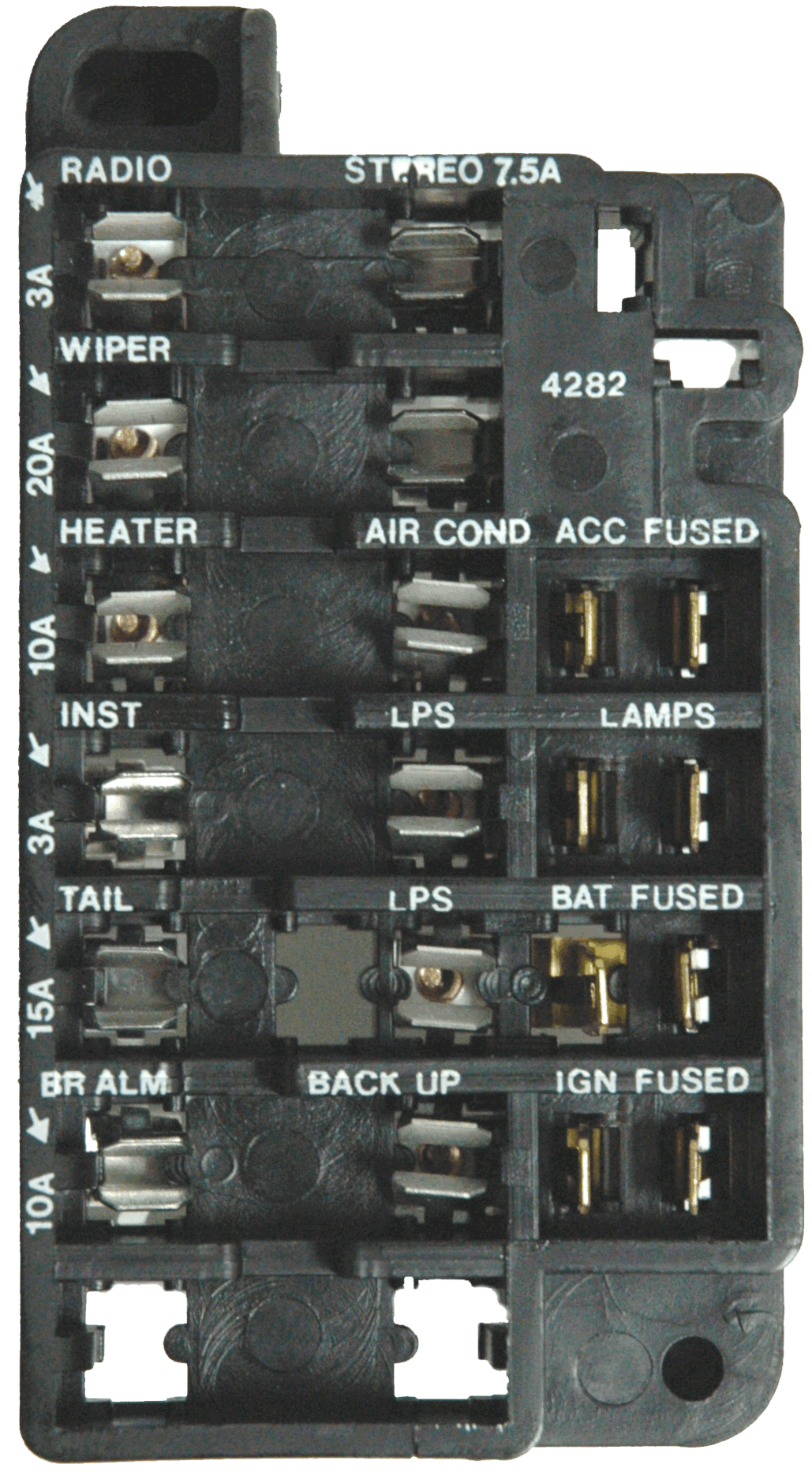
Both the amperage rating, as well as and the type of fuses we supply in our fuse kits ARE correct for your car. We know and understand that the amp rating that is silk screened on your fuse block may not necessarily match the amp rating of the fuses we supply in our kit. We also recognize that the there may be discrepancies between what we supply in our kit and what is called for in the owner's manual or service manual.
Believe it or not the fuse blocks were not always screened properly for a specific year/make/model vehicle, and as many of you are aware, owner's manuals and service manuals are not always correct either.
We get our fuse information directly from the original assembly manuals. The assembly manual showed the assembly-line worker what fuses (based on part #) to install in the vehicle's fuse block. Notice that the assembly manual does not even show the screen printing on the fuse block. It simply shows the part # and location for each fuse.
Some of the connectors in our Engine and Forward Lamp Harnesses are injected with a special tar-like material, as they were originally.
When mated with the bulkhead connector mounted on the firewall, this tar/grease prevents corrosion from forming on your terminals, and acts as a vapor and moisture barrier. Do not remove this grease or allow the grease to come in contact with your clothing. It will stain.

There was a recently discovered change by General Motors (and part manufacturer CASCO) in their 1966 and older Corvette current replacement cigarette lighter housings. This change could cause the housing to short circuit and thereby burn the wiring harness. The change is a small bi-metal element added to the rear of the housing where the power wire connects. It was added as an additional safety feature for cars with a fused cigarette lighter. The problem is that 1953-66 Corvettes DO NOT have a fused cigarette lighter. Power to the lighter comes directly from the battery.
When installing this replacement cigarette lighter housing in a 1953-66 Corvette, you MUST REMOVE the bi-metal element!
The result of installing this replacement housing, without removing the bi-metal element, is a dead-short that will cause your wiring to burn!
The original GM part number for the lighter housing is 3986869, replaced by 11516142. Virtually every Corvette parts supplier uses this same housing, so any owner of a 1953-66 Corvette should check the housing and remove the bi-metal element if present.
More information on this Cigarette Lighter Alert, courtesy of Corvette Central.
Help With Installation
There are several ways in which to replace an existing wiring harness with a new harness. We recommend that you install your new harness as you are removing your old one. This way, you can be more certain that the wires are routed as original and that the wires are going to their intended devices.
If you decide to first completely remove your harness, you may want to do the following: When removing your old harness from the car, remember to mark where the original wires were connected and/or take reference photos. We also suggest that you have a 'Factory Assembly Manual', if available for your year/make/model. (Note: A 'Service' or 'Shop' Manual will usually not provide any information on harness routing). The Factory Assembly Manual contains general overview schematics, as well as line drawings of how to route the harnesses within your car. This manual is what the factory assembly line workers used to properly route the wires. They are available from your local restoration parts supplier and will simplify the installation of your new harness.
If you have any questions regarding 'what goes where' on your Lectric Limited harness, call our technical support line for installation tips.
Note that some of our Engine and Forward Lamp harnesses utilize a special di-electric grease as original. This grease is smothered inside the bulkhead connector that mounts to the firewall. Do NOT remove this grease; it is a corrosion inhibitor. Do not allow this grease to come in contact with your clothing. It will stain.
Every Lectric Limited wiring harness has a white assembler's tag on it. This identifies the harness to us for tracking and troubleshooting should there be a problem. We recommend that you leave this tag on. However, if you want to remove it please Do NOT remove this tag until the harness is installed and working properly.
For most 1982 and earlier GM vehicles, the Purple wire with the ring terminal goes to the 'S' (solenoid) small stud post on the starter solenoid.
The other wire, if applicable, with the same size ring terminal as the Purple wire, goes to the 'R' (run) or 'C' (coil) terminal on the starter solenoid. This wire color can be Yellow, Pink, Green, Black w/Pink stripe, or Black w/Yellow stripe.
The wire with the large ring terminal goes to the 'B' (battery) terminal post (large post) on the starter solenoid. This connection may contain 1 or more wires, usually a heavy 10 to 12 gauge wire or fuse link wire. These wires could be Black, Red, Red & Black, or Fuse Link in the following colors: red, orange, brown or black.
The Black wire, usually 14-16 ga., and usually breaking out of the harness 6 to 10 inches before the wires listed above, goes to the starter motor mounting bolt or bell housing bolt (ground).

First of all, getting your hands behind your dash can be a bit of a struggle. But your task will be much easier if you follow this removal method.
These lamp sockets were designed with 2 flat sides. Get a 7/16'' open-ended wrench and slide it into the flat sides of the socket. Use a twisting motion to pop-out the socket.
Do not pull the socket straight out! Doing so may separate the metal retainer from the plastic socket, and the socket will be ruined.
On occasion we get phone calls from customers stating that a wire or two from our harness does not reach their intended device or 'the wires are too short!'. This is usually due to the fact that the customer does not route the wires correctly. Routing a wire over something instead of under it, can make a big difference.
As a reference, we recommend that you purchase a Factory Assembly Manual (not a Shop or Service Manual). The Assembly Manual is what the factory assembly line workers used to properly route the wires - so they reach where they are supposed to. However, on rare occasions, we've found that the Assembly Manual is NOT always correct. (go figure). So please keep this in mind. If an assembly manual is not available for your vehicle, then you would need to look at an original car for wire routing information.
On other occasions, purchasing an aftermarket product can lead to the problem. For example, if you use an original Horn in your 1963-67 Corvette, your new wiring harness will reach the second horn and work perfectly. If you use an aftermarket or incorrect replacement horn, the terminals on that horn were not placed in the original location. And in this case, the wires leading to the horn will not reach if routed as original.
As we state throughout our website, we manufacture all of our wiring harnesses to the original blueprint specifications. So they're correct! In the above situation, you would either need to purchase an original horn, make the wiring modification yourself, or determine a way to make the wires reach.

A battery disconnect switch makes it convenient to isolate the battery from any potential draws when the ignition switch is off (like a clock, radio display, glove box light, computer, etc.) and it's much more convenient to turn a knob or move a lever than to keep removing the battery cables from the battery.
You also want to remove the battery as a power source when doing any work on the car that involves the electrical system, especially on earlier cars that have many un-fused, ignition-off, battery-fed circuits and don't have fusible links on the primary power feed circuits; harnesses are expensive, and dead shorts can cause a fire.
Battery disconnects are designed to be installed on the NEGATIVE (Ground) battery terminal. The negative battery terminal is smaller in diameter than the positive terminal. Correspondingly, the battery disconnects have the smaller hole where they attach to the battery (and the smaller terminal size where the negative cable attaches to the disconnect switch).
Electrically speaking, it doesn't matter if you disconnect the positive or negative side of the battery. But safety is another matter.
Disconnecting the positive side will kill power to the harnesses, but there's still a ground path back to the battery. If you drop a wrench and it touches the battery positive terminal and the engine, it will create a 500 to 700-amp dead short - which could damage (or destroy) your battery (and even melt your wrench).
If you disconnect the negative side (as all disconnects are designed to do) and drop a wrench that touches the battery positive terminal and the engine, nothing will happen, as there is no ground path from anything in the car back to the battery to complete the circuit.
It's Not Working (General Problems)
Assuming your temperature gauge, temperature sending unit, and wiring is not defective, a cause of inoperable or intermittent gauges is because of the use of Teflon/pipe tape sealant on the sending unit's threads.
Do not use Teflon tape, thread sealant, or any other material on the threads of your sending unit!!! Screw the sending unit right into the engine. If you must use something to keep your sending unit from leaking, you can use pipe thread sealant, but do so sparingly.
Any material between the threads of the sending unit and the car's ground (engine) can result in your gauge working improperly, or not working at all. Without the sending unit being grounded, your temperature gauge will show an approximate 100 degree reading (pegged to the left, cold side, of the gauge) no matter what the engine's temperature. If your sending gauge is making a poor (high-resistance) ground to the engine because of Teflon tape or pipe thread sealant, your gauge will read cooler than the actual engine temperature.
Also, you should never over-torque the nuts on the back of your temperature gauge. A very fine winding wire is attached to the back of those nuts. Over-torquing the nuts will tear this fine wire from the inside of your gauge. This is a VERY COMMON mishap. This will cause the gauge to either not display or possibly jump up & down as you are driving (because the gauge wire is making & breaking electrical contact).
Did you know Lectric Limited offers accurate replacement Temperature Sending Units that will perform as-original? These sending units will make your temperature gauge read accurately (provided you have resolved the possible problems shown above).
Part 1 of 2
The 1st possible problem:
Your temperature sending unit is defective or is the wrong type (wrong resistance/thermistor).
Most likely you, or a previous owner, had installed a generic sending unit. Auto supply stores carry generic sending units that will fit and function in your engine,. But because these sending units cover a broad range of years/makes/models, they do not have the same precision resistance rating as the factory sending unit specifically designed for your year/make/model car.
These generic replacement sending units may either work, or may give inaccurate readings. It would now be up to you to determine if your gauge displays an accurate reading.
We can solve your first problem. Lectric Limited offers accurate replacement Temperature Sending Units that will perform as-original. These sending units will make your temperature gauge read accurately (provided you have resolved the following problems).
The 2nd possible problem:
If your temperature gauge originally had a resistor bridging the silver post (ground) and the copper post directly across, this resistor may be missing. This is typically a 90 ohm ceramic resistor and must be used.
To the right is a diagram of how a typical temperature gauge should be wired.

If the value of the resistor, on the back of the gauge, bridging the silver post and the copper post directly across, is too high, your gauge will read hotter than the engine's actual temperature. With no resistor (high resistance state) your gauge will peg to the right. (Note: The correlation between resistance and the gauge display is exactly the opposite when adding more resistance in series with the sending unit. If you add more resistance in series with the sending unit, your gauge will display cooler than the engine's actual temperature.)
If the value of that resistor on the back of the gauge is too low, your gauge will read cooler than the engine's actual temperature. With shorted terminals (no resistance state) your gauge will peg to the left. (Note: The correlation between resistance of the sending unit and the gauge display is exactly the opposite. If you could subtract the resistance of the sending unit, your gauge will display hotter than the engine's actual temperature.)
The 3rd possible problem:
You do not have your gauge wired properly. Below is how a typical temperature gauge, with 4 terminals, should be wired. Also shown are 2 ways that you can 'fool' your gauge to display/read cooler. Although we recommend using the correct temperature sending unit, adding an external resistor is an option.
WARNING!!! Jury rigging your car's temperature reporting system to force it to read 'accurately' under normal conditions without first understanding which component(s) of the system are off can be very dangerous. For example, if you 'fix' a temperature gauge with a 50 ohm resistor, when in fact the gauge was operating correctly, could result in your gauge displaying an acceptable 190 degrees (normal driving temp.) when your car is actually operating at a dangerous 260 degrees. Use your discretion.

The 4th possible problem:
Sometimes, in order to correct an inaccurate gauge reading, previous car owners have been known to install a resistor in series with their temperature gauge. Unknown to you, you may have a hidden resistor somewhere between your temperature sending unit and gauge. Additional resistance will cause your gauge to display/read cooler than the actual engine temperature. This resistor needs to be removed in order to give you an accurate gauge reading with our new, accurate sending units. NOTE: Here is a great article about Water Temperature Gauge Accuracy. Be sure to check it out!
The 5th possible problem:
Did you use Teflon tape or pipe thread sealant on the threads of your sending unit? If you did, try removing it and see if that corrects the problem. Note: If you must use something to keep your sending unit from leaking, you can use pipe thread sealant, but do so sparingly.
Any material between the threads of the sending unit and the car's ground (engine) can result in your gauge working improperly, or not working at all. Without the sending unit being grounded, your temperature gauge will show an approximate 100 degree reading (pegged to the left, cold side, of the gauge) no matter what the engine's temperature. If your sending gauge is making a poor (high-resistance) ground to the engine because of Teflon tape or pipe thread sealant, your gauge will display/read cooler than the actual engine temperature.
Part 2 of 2
IT'S A FACT that the original 1963-65 Corvette (and possibly other GM vehicle's) temperature gauge was not accurate!!!
The gauge displayed a reading that was higher than the actual engine temperature. Consequently, your car may be within standard operating temperature even though your gauge reads hot. Click Here for the actual Technical Service Bulletin (TSB), issued by Chevrolet in November 1965, addressing this flaw.
The internals of the 1963, '64 & '65 temperature gauge were electrically the same.
The '63 was cosmetically similar to the '64, but much different than the '66 gauge. Therefore, replacing a '63 or '64 gauge with a '66 gauge was unacceptable for many owners. However, since the '65 gauge was cosmetically similar to the '66 gauge, the '66 gauge (that functioned properly) was a suitable replacement for the '65 gauge.
We can only assume that this is the reason the TSB does not specifically address the 1963-64 Corvette gauges, even though the gauge flaw applied to those years.
Please note that our replacement temperature sending unit will not correct this factory flaw. To correct the flaw in 1963-66 Corvette gauges, you may need to install a 270 - 330 ohm, 1/4 watt ceramic resistor across the 2 posts. This should supply your gauge with the correct resistance in order to read more accurately.
A resistor may be added to make your 1963-82 (approx.) gauge read cooler, and closer to the actual engine temperature (thus compensating for the gauge flaw). There are 2 options shown:
- OPTION #1: Using 330 ohms as a base line (meaning to start with a 330 ohm resistor), the more you decrease the resistance, say from 330 to 270 ohms, the cooler the gauge will display. In effect a 270 ohm resistor will make your gauge read slightly cooler than by using a 330 ohm resistor - with the resistor placed between the 2 posts as shown in the diagram above. We do not have specifications correlating ohms to temperature. You will just have to try different value resistors until your gauge displays the actual engine temperature. CAUTION: Do not install too low a value resistor, or you may short-circuit the posts. NOTE: Do not confuse the resistor of this value and in this location (between the 2 posts on the gauge itself) with the resistor mentioned in Option #2 (below).
- OPTION #2: On any gauge, you can add a resistor at some point between your temperature sending unit and your gauge. The higher the resistor value, the cooler your gauge will display. We do not have specifications correlating ohms to temperature. You will just have to try different value resistors until your gauge displays the actual engine temperature. A suggestion is to start with a 5 or 10 ohm resistor. Keep adding resistance until you get the desired gauge reading.
Almost all of the time, your problem can be resolved by addressing the issues shown below:
(Part 1 of 4)
- Did you know that many times a problem with an original T.I. system can be traced back to the electronic components. Many years ago, when the T.I. system was developed, Germanium transistors were 'state-of-the-art' in electronic technology. This type of transistor, however, had many limitations and many amplifier failures can be traced back to these transistors. Our VTR6571AM replacement module uses the newer type Silicone transistors that rarely fail. Other problems that led to amplifier failure were due to water from a faulty cover seal. Moisture trapped inside the amplifier box will cause corrosion to the extent it will rust electrical component leads and destroy copper tracks (traces) on the printed circuit board, thus leading to failure. All of the electronic components in our VTR6571AM are completely encapsulated/sealed. If water does get trapped inside your box, the VTR6571AM will not be effected.
- If you install one of our VTR6571AM modules and are having problems with your T.I. system not functioning, 99% of the time the problem lies in the female terminals in the Amplifier Box Extension wiring. This wiring connects the module to your wiring harness. The electrical connections must be perfect - there is a very small tolerance within the T.I. system for any unnecessary resistance. The electrical connections are the weakest link in this system.
- Over the years, the spring-tension on these female terminals WILL loose their 'grip' on the male terminals they connect to. The T.I. system draws up to 7 amps so it needs all the current it can get. And a voltage drop of only a 1/2 volt will cause your module to fail. It is IMPERATIVE that the Amplifier Box Extension wiring be replaced when installing a new T.I. Box Module. Don't fool yourself into thinking 'My old wiring looks good. It'll be fine'. It won't be!
We offer two different T.I. Amplifier Box Extensions. The Lectric Limited part #VTR6468BXT is for 1964 to early 1968 Corvettes, 1966 Chevy II/Nova, 1964-66 Tempest/Le Mans GTO, 1964-66 Pontiac Full-Size. Part #VTR6871BXT is for 1968 (2nd design) thru 1971 Corvettes and 1969 Camaros.
(Part 2 of 4)
Another cause of a non-functioning replacement T.I. Box Module (our VTR6571AM) can be corrected by simply charging your battery. An original T.I. amplifier board requires .4 to .7 volts AC to begin 'switching'. Our replacement T.I. amplifier box module (VTR6571AM), with more robust circuitry, requires at least 1 volt AC to switch. This may not sound like much of a difference, but it equates to about 40% more voltage. Therefore, when cranking your engine, if your battery doesn't spin your starter (and distributor) fast enough, and/or the pickup coil is not generating the minimal required AC voltage, the ignition system will not function. So keep your battery fully charged.
(Part 3 of 4)
Are you using the right ignition coil? Another cause of a non-functioning T.I. system may lie within the ignition coil. The T.I. coil is unique to this system as it is powered by a higher primary voltage and has a greater number of secondary windings than a 'points system' coil - creating greater spark energy. Keep in mind that a points ignition system switches the coil's negative terminal. A T.I. system switches the coil's positive terminal.
(PART 4 of 4)
And finally, check your grounds!!! Corvettes (being made of fiberglass) are very prone to grounding issues.
A possible problem is a:
- ammeter/voltmeter wired backwards
- faulty switch or relay
- stuck relays
- defective alternator/generator or voltage regulator
There is NOT a problem with your Lectric Limited harness. This is 'normal' (so to speak). The original wiring for a 53-62 Corvette was, in fact, not designed properly by GM. The problem is a result of inadequate grounding, compounded with RFI signals being sent through the power circuits to the gauges.
Numerous studies have determined that there's nothing you can do about this problem with the existing, original wiring. Even by adding additional grounds, this problem will not be corrected. It's a GM design flaw you'll just have to live with. :-)
You probably have one or more of the following problems:
- bad bulb(s)
- incorrect bulb(s)
- defective signal flasher
- wrong signal flasher
- bad wiring
All of the above are critical in the correct operation of the flashing circuit.
A note about bulbs...you can NOT interchange 2 contact bulbs for single contact bulbs. They may physically fit but will either not work properly or blow a fuse.
For some cars, we offer complete fuse & flasher kits with all the properly rated fuses and lamp flashers. View Catalog for your application.
Sometimes the symptoms of an electrical problem just don't make any sense. Intermittent instruments, lights flashing that are not connected to the turn signal circuits, a dome light coming on when the brakes are used, a radio coming on when the turn signals are used, and general weirdness usually means one thing - someplace, somewhere there is a 'floating ground', and electrons are looking for any path they can use to get back to the battery.
Many times critical ground wires are left off when doing a restoration. Or, the underside of the terminals that ground the chassis, engine, etc., are corroded or not securely fastened. If corrosion is the problem, it might not be apparent until the terminal is removed and examined.
Make SURE that the chassis, engine, and any other place that must be grounded has a good solid ground to the negative side (ground) of the battery.
The old saying still holds true...'Check your grounds!''
Note: We sell ground strap sets for many applications. View Catalog for your application.
Let's make the assumption that you just installed a new Lectric Limited harness. Our harnesses are circuit tested to insure that the harness is factory perfect before you install it. That being said, the most common problems is a faulty 1.) horn relay, 2.) voltage regulator 3.) generator/alternator.
It has been our experience that when a customer has burned-up their harness, and they check the continuity of the terminals posts on their horn relay, voltage regulator, and/or generator/alternator, they find that at least one is shorted to ground. A harness that's shorted-to-ground will take only seconds to burn.
It may be that the 'rebuilt' horn relays currently being sold are, for the most part, only re-plated and re-painted. They are certainly not electrically tested, and don't include new windings and contacts.
DO NOT make the assumption that just because you purchased a 'rebuilt' horn relay it will be 'as new'. The same is true for voltage regulators and alternators.
The body of a Corvette is made of fiberglass, which does not conduct electricity. Therefore, the integrity of the entire grounding system must be perfect, with all the component and chassis grounds in place and corrosion-free. As the old saying goes, 'Check your grounds'. This is more true for a Corvette than for any other car.
You can consult a factory 'Assembly Manual' (not a shop or service manual) for the location of these ground wires. We do offer some ground lead wires and ground strap sets.
Finding an electrical short can be one of the most frustrating and time consuming problems in owning an antique vehicle (or any vehicle for that matter). But where do you start to isolate the cause of the problem?
Here's the scenario: Everyday or two you have to jump start your car because the battery has drained down to the point where the car won't start.
As with all scenarios, we have to make some assumptions. We have to assume that your battery is good and was fully charged, that your charging system is good, that you are not blowing fuses or fusible links, that you did not leave any lights on (interior, glove box, under-hood, etc.) and that you did not leave your car's ignition in the 'run' position with the engine off. If all these were checked, you probably have something that is drawing enough power to drain the battery (short?), but not sufficient enough to blow a fuse or fusible link in a protected circuit.
Let's try to locate the possible short. If you have a test light (easily obtained at any auto part's store) disconnect the negative battery cable from the battery. Connect the lead from your test light to the negative battery cable and connect the other end of your test light to the negative battery post. An assistant or 2 small hose clamps will help hold your test light in place. (An ammeter (not a voltmeter) will be a more accurate substitute for a test light assuming you can read an ammeter. Normal constant draw on the battery is about 200ma.)
On your test light, you may get:
- No light. This means no power draw (no problem) or a bad connection on your test light (fix & re-try).
- A quick flash of the light, then nothing. This may be normal as the capacitors in the electronics charge up.
- Constant light. This is probably what most people will see. Whether you have a problem or not. Small devices like clocks, radio displays, etc. will constantly draw a SMALL amount of power and cause the test light to dimly glow. This is normal. If your test light glows very bright, you have a problem with something drawing too much current.
Keep the car doors closed (or the door jamb switches depressed) and remove the under-hood light bulb.
First, disconnect all wiring to the alternator (the main cable and one/two plugs). If the test light glows dim or is off completely, you've found a problem. There's an internal fault in the alternator. This can happen even if the system is charging the battery. Have your local auto parts store bench test your alternator and repair or replace if necessary.
If your test light still glows bright, start by pulling each fuse, one at a time. With each fuse pulled, watch the test light. If it goes dim or off, you've probably isolated the harness (engine harness, dash harness, forward lamp harness, etc.) causing the problem. If the test light still glows bright, re-insert the fuse and remove the next fuse and watch the status of the test light. If after removing all the fuses, your test light still glows bright, then disconnect each fusible link, one at a time. NOTE: If you think you've found the harness or circuit causing the problem, it is wise to complete the test and remove every fuse, one at a time, noting the test light status. It can be a compound problem spanning multiple harnesses.
Once the specific harness is isolated, you now need to locate the specific circuit within that harness causing the problem. Find out what the involved fuse(s) are for and trace it from there. A wiring diagram is extremely helpful here, but common sense can find many problems without a diagram. The most likely culprits are bad switches to the interior lights (to include the trunk & glove compartment).
If you still can't locate the problem after completing these tests, your next step is to take your car to a qualified mechanic who specializes in electrical systems.
It's Not Working (lectric Limited Products)

ALL of our temperature sending units are manufactured with the same thermistor (internal sensing device), 1/2'' (not 3/8'') diameter pipe thread, and top terminal connection as original. Through the years, the mating terminal & connector on your harness may have been changed by you or a previous owner. This change was most likely made in order to try different sending units when the 'exact replacement' unit didn't work or was not available. If your harness had been modified from original, we do offer replacement Temperature Sending Unit Lead Repair Kits. (See our “Repair Components” section.)
In addition, part# 01513321 (with the 'T' shaped terminal) was typically used on cars with the sending unit positioned in the INTAKE MANIFOLD.
All the other sending units, shown above, were typically used on cars with sending unit in the CYLINDER HEAD. This straight-in type connection either prevents the sending unit wire from rotating, or, if the wire can rotate (as with sending unit #01513130), will not rotate in such a way as to come in contact with the hot exhaust manifold and melt.
The point were trying to make is that when a customer calls and says, 'You sent me the wrong sending unit. The sending unit I'm supposed to have looks like the 01513321 'T'-type, but you sent me a 01513462 threaded-post type.'' The first question we ask is, 'Where does your sending unit screw into?'. If they say the cylinder head, then we know the customer is mistaken. We know this because GM would never use a sending unit that could allow the sending unit wire to melt on the hot exhaust manifold.

Let's face it, even though we restore and maintain our classic cars, we are dealing with 30-50 year old technology and many times original components (gauge, wiring, voltage regulator, alternator/generator, etc.). Yet the temperature accuracy of a new car's temperature gauge is only slightly more accurate than in the past.
If you look at your classic car's temperature gauge, you'll note there are very few temperature reference points. You'll see something like a 100-120 deg. F indication at the low end, a mid-scale 180-210 deg. F area, and a somewhat detailed high end warning area in the 230-260 deg. F range. Why? Because GM (and most other manufacturers) was not trying to design a precision thermometer found in a laboratory. GM was looking for an inexpensive, high-production-run system that would give the driver a reasonably accurate visual indication of the mid-range engine temperature, and accurately predict a bona fide engine overheating threat. (You can forget about accuracy below 140 degrees.) So as long as your vehicle was not over-heating, GM was not concerned if your gauge displayed 198 degrees, as opposed to the true temperature of 220 degrees, for example.
Without getting into to much technical mumbo-jumbo, all automotive sending units are calibrated on a 'temperature vs. resistance' ratio scale that is exponential (a curve) and not linear (a straight line).
The response curve of the temperature sending unit is 'bounded' by upper and lower exponential curves. These curves form an 'acceptable' range where individually manufactured parts can vary in precision. This is what is called the '+ or -' accuracy range. The acceptable range is wide at low temperatures (around 120 deg. F) and is refined, or more accurate, at the high end of the gauge (around 230-260 deg. F).
NOTE: This exponential curve of temperature vs. resistance is why you can not determine if your sending unit is good or bad by taking a resistance (ohm) reading below, say 180 degrees. If you do, your assumptions as to the accuracy of the sending unit at operating temperature will not be correct.
So, if your true engine temperature is 220 degrees F. Assuming all other conditions that effect a gauge reading are operating perfectly, an original GM sending unit will display a gauge reading between 198 deg. and 242 degrees. This is a + or - 10% accuracy. This is considered an acceptable display range. All Lectric Limited's sending units meet, or perform better than this GM specified range. In addition, we quality control test all our sending units at the time of manufacture.
In accordance with the original GM blueprint specifications, all Lectric Limited's sending units are manufactured to tolerances as follows:
- 520 ohms + or - 20% at 100 deg. F
- 81 ohms + or - 10% at 220 deg. F
Please understand that it is the design of the entire temperature detecting system (not just the sending unit), and the variances of the components within this system, that effect the accuracy of your gauge reading. Any one of the factors below can effect the accuracy of your temperature display:
- Temperature gauge (calibration, windings, proper or missing gauge resistors, if applicable?)
- Sending unit (auto part's store replacements and over-the-counter GM replacements are not accurate for early cars)
- Alternator/generator (proper output voltage?)
- Voltage regulator adjustment (proper output voltage?)
- Battery charge condition (fully charged?)
- Wiring (high resistance in wiring or between terminal contacts?)
- Material on sending unit's threads (there should be no Teflon tape or pipe thread compound used) Note: If you must use something to keep your sending unit from leaking, you can use pipe thread sealant, but do so sparingly.
- Air in the cooling system (Did you recently change the coolant and not given the system a chance to purge itself of air pockets?)
- Inaccurate detection points to measure engine temperature. (We get calls from people who take readings from all over the engine: the upper radiator hose, lower radiator hose, the radiator itself, the thermostat housing, the head, the block, at the base of the sending unit, etc., etc, etc. Of course, at each of these points there will be some variance of the true engine temperature. Although there is no 100% accurate method to measure the engine's internal temperature from external detection while the engine is running, we feel that you can get a somewhat accurate reading by using an infra-red digital thermometer (shown below). But, as you will experience, your readings may differ with each trigger-pull. But for the optimal temperature reading, while the engine is at operating temperature, point the infra-red thermometer at the lowest point of the thermostat housing, just above the gasket. If you point the thermometer at the base of the sending unit, you may be reading the additional heat given off by the exhaust manifold.)

Most, if not all, of the 'exact replacement' sending units available at an auto part's store, and currently from GM for that matter, are not accurate. They far exceed the 10% tolerance range mentioned above. It is for this reason that Lectric Limited researched the project and developed sending units that produce an accurate gauge reading within a vehicles operating temperature, + or - 10% tolerance.
I know that today's sophisticated driver wants his/her gauge to display a laboratory-accurate reading, but the design inadequacies of the entire system do not allow for pin-point accuracy. But if you want your gauge to display as accurately as possible, install one of our replacement sending units, or a working original sending unit, and address the factors mentioned above.
NOTE: Here is a great article about Water Temperature Gauge Accuracy. Be sure to check it out!
(Part 1 of 5)
CHECK YOUR GROUNDS:
A bad or marginal ground connection to the distributor's breaker plate is by far the most common problem. This wire can be found under the breaker plate of the distributor. Every time the vacuum advance moves the point plate, your existing ground wire is flexed. This will eventually cause fatigue cracks inside the wire insulation or near the terminals. This is also true for the point wire, since it also flexes when the plate moves.
If the wiring is several years old, it should be replaced using a high flexibility (high strand-count) conductor with high temperature insulation.
As stated, a bad or marginal ground is most often the answer to the problem of a non-working Breakerless-SE module. The Breakerless-SE is more sensitive to ground conditions than the old points were. So when a customer says 'My car worked fine with the points but I get no spark after installing the Breakerless-SE.' We tell them, 'Remove the breaker plate and check the ground wire to the breaker plate. Make sure the ground wire and terminals are not corroded and that the wire is not cut. Remove the wire and clean the terminals and the area under the terminals to insure the integrity of the ground'.
If you are sure you've checked this ground wire and are still having problems, please read PART 2 below.
(Part 2 of 5)
ROTOR:
If the car started with the points, but not after installation of the Breakerless-SE module, check that the rotor was modified per the installation instructions, re-installed and indexed correctly and that the battery ground cable was re-attached. If the distributor was moved, the timing may be too far advanced or retarded. Set the timing statically, as described in the instruction sheets./p>
DISTRIBUTOR:
NOTE: As stated above, a bad or marginal ground connection to the distributor's breaker plate is by far the most common problem with the Breakerless-SE not operating at all.
Also, if you had painted your distributor, intake manifold, or block, make sure that there is a paint-free contact area between all of these components. If not, you may loose your distributor's connection to ground.
COIL:
If all of this looks OK, use a test light to verify there is voltage present between the coil's (+) terminal and ground, with the key in both the start and run positions. Loss of voltage may be due to blown fuse, faulty ballast resistor or improper wiring. With the key in the run position and the engine stopped, check that voltage is also present where the point wire connects to the module. This will verify continuity though the coil primary and the point wire.
Last, connect one lead of the test light to battery (+), and touch the other end to the point plate to verify continuity to ground. Note! Before beginning any tests, always first check that your test light works by connecting it across the battery.
If a bad coil is suspected, it should be replaced or a live spark test can be performed. (A coil testing procedure is shown below in PART 3)
WARNING! The coil generates extremely high voltage, which can be lethal. For safety and convenience, use the test procedure outlined below, or as described in your shop manual. Do not perform this test if fuel vapors or any combustible materials are present.
You will need to purchase a calibrated standard ignition test plug to perform this test. These are manufactured by the K-D Tools company (K-D part# 2757) and are available at most auto parts stores for under $10. This plug forces the coil to generate a known voltage, providing an accurate pass/fail evaluation.
Turn off the ignition switch. Remove the high voltage wire from the coil. Remove one spark plug wire from the car and attach it to the test plug. Insert the other end into the coil. Clip the test plug to the hood hinge on the driver's side.
Crank the engine over. The spark should easily jump the gap and will vary in color from blue (strong) to yellow (weak) depending on the output of the battery during cranking, as well as several other factors (you may need to do this test in a darkened area).
If you are sure you've checked this ground wire and are still having problems, please read PART 3 below.
MODULE:
If all this checks out, the coil or the Breakerless-SE module may be suspect. To test the module, remove the point wire from the coil (-) and attach it to the test light. Connect the other end of the test light to +12 volts. The light should blink rapidly while the engine is being cranked, and go out when the engine stops. If the light does not come on, or stays on when the engine is stopped, the module should be sent in for further testing. Note! This test must be performed with a test light; a voltmeter will not provide correct results.
(Part 3 of 5)
Make sure that you have inspected the following:
CHECK YOUR GROUNDS:
Check all your engine block grounds! Make sure they are securely fastened to the frame. The old saying still holds true...'Check your grounds!' These ground wire or ground straps MUST be clean and without corrosion on the wires or terminals.
COIL:
NOTHING can (or should be) attached to the positive (+) side of the coil except the ballast resistor or resistance wire. (For example, do not attach an electric choke, alarm system power supply, etc. to the + side of the coil. You will be drawing current through the ballast resistor or resistance wire which will effect the supply of current to the Breakerless-SE module).
NOTHING can (or should be) attached to the negative (-) side of the coil except the body ground. (For example, do not attach a tachometer directly to the coil. It will interfere with the operation of the Breakerless-SE module).
You should be using the proper coil. The Breakerless-SE was designed for classic restoration cars. Consequently, the Breakerless-SE is compatible with all original/stock GM Delco Remy coils when used in conjunction with the factory installed ballast resistor. These original-type coils are high-inductance and have a primary resistance of 1.2 to 2.8 ohms.
Most aftermarket or 'hi-performance' coils are compatible as well, as long as their primary resistance is within the range of 1.2 to 2.8 ohms. The Breakerless-SE will perform at its best when using a coil with a primary resistance of 1.3 ohms.
How can you tell what the primary resistance of your coil is? You can get this information from the coil's box, contact the manufacturer, or use a quality ohmmeter on the coil.
To check your coil, disconnect all the wires attached to the coil. 'zero' your ohmmeter. Then connect your ohmmeter across the (+) and (-) posts of the coil (this is the primary winding). This primary resistance reading should be between 1.2 and 2.8 ohms. Next, connect your ohmmeter between the (+) side of the coil and the coil's center post (this is the secondary winding). This secondary winding reading should read about 7000 ohms.
Be sure to follow the coil manufacturers installation instructions carefully, or contact them whenever installing a non-stock coil. Before you buy a new coil, you will want to contact the manufacturer for compatibility issues.
NOTE: DO NOT use the Breakerless-SE with any MSD Blaster coils or coils with low primary resistance. The primary resistance on these coils is too low (about 0.5 ohm) and will ruin the Breakerless-SE module and void your warranty!!!
BALLAST RESISTOR:
MAKE SURE that you have the proper ballast resistor or resistance wire installed. For 1966 & under years GM cars, the resistance across the ballast resistor or resistance wire should be 1.8 ohms. For 1967 & up year GM cars, the resistance across the ballast resistor or resistance wire should be 1.3 ohms. The Breakerless-SE works optimally with 1.3 ohms resistance.
How can you check if you have the properly rated ballast resistor or resistance wire in your car, or if it's even any good? First disconnect all the wires going to the ballast resistor. Connect a QUALITY digital ohmmeter or, ideally, an oscilloscope across the 2 posts. (Make sure you 'zero' the meter before testing.) If testing resistance wire, connect your meter where the resistance wire starts and ends. The resistance reading (ohms) you get should match that stated in the above paragraph.
You need to check resistance! You can not simply check the voltage reading at the coil, and with this reading make assumptions about the value or integrity of your ballast resistor (or resistance wire). Checking voltage will not give you an accurate representation of the resistance, unless you have a sophisticated oscilloscope and know how to use it.
Do NOT operate the Breakerless-SE without the proper ballast resistor or resistance wire installed! The proper ballast resistor or resistance wire must be used.
If you are sure you've checked this ground wire and are still having problems, please read PART 4 below.
(Part 4 of 5)
Do NOT use any di-electric grease or heat sink compound on the bottom of the Breakerless-SE module.
It is not necessary. And it can cause the Breakerless-SE module to function erratically or not function at all. As stated above, it is critical that the Breakerless-SE module has a good, solid ground. Any type of grease applied between the bottom of the module and the breaker plate will cause problems.
If you already applied the grease, remove it. Then wipe the entire area clean with alcohol or acetone to remove any greasy residue.
(Part 5 of 5)
Recently, we have discovered that there is a company manufacturing 'reproduction' ballast resistors. Unfortunately, 10 out of the 10 ballast resistor we tested are out of spec. and have a resistance that is too high. This equates to a voltage that is too low at the coil; which will cause your Breakerless-SE not to operate properly or not operate at all.
If you installed the Breakerless-SE your car would either have a ballast resistor or a resistance wire. The resistance on the ballast resistor or resistance wire should be checked. The Breakerless-SE works optimally with 1.3 ohms resistance.
Cars with a Ballast Resistor: If your car has a ballast resistor, you need check the resistance while the resistor is at operating temperature (warm/hot). Let the car run for awhile to get the ballast resistor warmed-up. While the car is running, so as to not allow the resistor to cool, place one probe of your multi-meter on one lead of the ballast resistor, and the other probe on the remaining lead of the ballast resistor. You should read a resistance of 1.2 to 2.8 ohms. If you don't, your ballast resistor is out of spec. or defective and must be replaced.
Cars with a Resistance Wire: If your car does not have a ballast resistor it uses a resistance wire. How can you tell which wire is the resistance wire? The resistance wire is the non-yellow wire at the + side of the coil *. If your car has a resistance wire, you need check the resistance while the wire is at operating temperature (warm/hot). To do so, let the car run for awhile to get the resistance wire warmed-up. While the car is running, so as to not allow the wire to cool, place one probe of your multi-meter one the wire (at the switch side). Place the other probe at the end of the wire (at the coil + side). You should read a resistance of 1.2 to 2.8 ohms. If you don't, your wiring harness needs to be replaced.
* Not knowing the history of your car, it's possible that the resistance wire on your car had been removed, if, for example, a previous owner installed an MSD ignition. The resistance wire must be removed when installing an MSD ignition system but must remain intact, as original, when installing the Breakerless-SE.
I must mention that a defective T.I. (Transistor Ignition) Amplifier Box Module (VTR6571AM) itself is extremely rare. Most often, a problem with the T.I. system lies elsewhere.
That being said, there are a few things to check when troubleshooting the T.I. system. But remember, its all or nothing - either it works perfectly, or doesn't work at all.
(Part 1 of 4)
If you install one of our VTR6571AM modules and are having problems with your T.I. system not functioning, 99% of the time the problem lies in the female terminals in the Amplifier Box Extension wiring. This wiring connects the module to your wiring harness. The electrical connections must be perfect - there is a very small tolerance within the T.I. system for any unnecessary resistance. The electrical connections are the weakest link in this system.
Over the years, the spring-tension on these female terminals WILL loose their 'grip' on the male terminals they connect to. The T.I. system draws up to 7 amps so it needs all the current it can get. And a voltage drop of only a 1/2 volt will cause your module to fail. It is IMPERATIVE that the Amplifier Box Extension wiring be replaced when installing a new T.I. Box Module. Don't fool yourself into thinking 'My old wiring looks good. It'll be fine'. It won't be!
We offer two different T.I. Amplifier Box Extensions. The Lectric Limited part #VTR6468BXT is for 1964 to early 1968 Corvettes, 1966 Chevy II/Nova, 1964-66 Tempest/Le Mans GTO, 1964-66 Pontiac Full-Size. Part #VTR6871BXT is for 1968 (2nd design) thru 1971 Corvettes and 1969 Camaros.
Read more about T.I. Components.
(Part 2 of 4)
Another cause of a non-functioning T.I. Box Module can be corrected by simply charging your battery. An original T.I. amplifier board requires .4 to .7 volts AC to begin 'switching'. Our replacement T.I. amplifier box module (VTR6571AM), with more robust circuitry, requires at least 1 volt AC to switch. This may not sound like much of a difference, but it equates to about 40% more voltage. Therefore, when cranking your engine, if your battery doesn't spin your starter (and distributor) fast enough, and/or the pickup coil is not generating the minimal required AC voltage, the ignition system will not function. So keep your battery fully charged.
(Part 3 of 4)
Are you using the right ignition coil? Another cause of a non-functioning T.I. system may lie within the ignition coil. The T.I. coil is unique to this system as it is powered by a higher primary voltage and has a greater number of secondary windings than a 'points system' coil - creating greater spark energy. Keep in mind that a points ignition system switches the coil's negative terminal. A T.I. system switches the coil's positive terminal.
(PART 4 of 4)
And finally, check your grounds!!! Corvettes (being made of fiberglass) are very prone to grounding issues.
The Green light may go out when the battery is fully charged (or it may not). This would be determined by many factors:
- condition of your battery
- its rated capacity
- degree of discharge
- age of battery
- sulfation (accumulation of lead sulfate on the battery plates)
- temperature
On a new battery or one that has not experienced the factors mentioned, the Green light should go out when the battery is fully charged.
On an older battery, one that can not hold its peak charge for a long period of time, the voltage will drop as soon as soon charger turns off, which will turn the charger back on again. Also, on an older battery, the Green light may remain on continuously. This indicates that the battery is continuously accepting a charge from the BBFC100.
A continuous Green light may also indicate that the charger has detected a battery problem - for instance, its ability to take or hold a charge. Sometimes a battery may be sulfated, and the sulfation is creating a high resistance to the current flow (ability to accept a charge). Or, perhaps the battery is deeply discharged (below 8-volts).
Both the BBFC100 and BBFC200 chargers only put out 1/2 amp of current. This low level of current is usually a very safe level even if your battery is being charged continuously.
Check your bulbs!!! You probably have the wrong bulb(s) in your lamp sockets.
If you can see 2 contacts in the base of the lamp socket, then you NEED to use the correct 2-contact light bulb (not a single contact bulb). The reason there are 2 contacts is because some bulb sockets have a hi-low filament and some lamp sockets (especially on Corvettes) are not grounded. With non-grounded lamp sockets, an additional wire/contact (ground) is used. If you attempt to use a single contact bulb in 2 contact lamp socket, it will cause an instant short to ground, and blow a fuse. This usually happens as soon as you open your door.
For some cars, we offer complete bulb kits with all the proper bulbs. View Catalog for your application.
If you purchased the turn signal switch from Lectric Limited or one of our distributors, there is probably nothing wrong with the switch. It may be that the turn signal housing, under the steering wheel, has come loose. The N.C.R.S. (National Corvette Restorer's Society) has written a 2 page article on the topic and how to correct the problem.

We have been made aware that occasionally customer's experience a problem when installing our reproduction (and even NOS GM) Alarm On/Off Switches. After a new alarm switch is installed, when the door is locked and the key removed, the alarm should be turned-on. But some customers state that while turning the key to lock their car everything works properly (alarm has turned-on) until the final fraction of a turn - when the key is in the position to be removed - that the alarm turns off again.
Our research has found no documentation as to what the GM assembly line workers did to correct this problem. But we do have a possible solution that can be found in the inner piece of the switch (yellow part on our switch below) that goes over the lock cylinder shaft. To modify this switch, using an Exacto knife or small blade to carefully remove (shave-off) a very small amount of the plastic in the area(s) shown below in red.
Should you modify your switch? If so, from which side should you remove material? How much material to remove? These questions would be up to you to decide, depending on your particular switch. In any case, if you do decide to modify your switch, remove only a very small amount of material at a time (about 1/1000''). If you remove too much material, the switch will be ruined. PLEASE NOTE: We are providing this instruction as a courtesy to those who experience a problem. Our reproduction switches are manufactured exactly as original, using the original GM tooling. If your alarm switch needs to be modified to function properly with your particular lock cylinder, we are not responsible for the modification. Modified switches can not be returned or refunded, and we have no further information to provide.
Do You Sell . . .
Yes. Although we don't suggest that you repair an old harness, we do carry 3 widths of the correct non-adhesive harness tape. Do not use adhesive-backed electrical tape! The heat generated in your engine compartment will cause the adhesive to 'melt', and the tape to unravel. And dirt will stick to the tape.
Non-adhesive tape, that we use to wrap all our harnesses, is designed to stick to itself, without adhesive. This non-adhesive tape was used on factory-original harnesses.
We do not.
On a daily basis, we get calls and emails from people asking to buy repair items for their wiring harness; with requests like, 'All I need is one connector.', 'I need one terminal.', 'I' need a 1-1/2' piece of resistance wire.'' The requests go on & on. So much so that we had to state on our website and phone system that except for the limited Repair Components in our catalog, we do not offer wiring harness repair items.
So why don't we sell repair components? On occasion, we’ve “tested the waters” in selling a repair component. But we found that it not only takes away from our harness sales (the reason we're in business), but often times the R&D to cross-reference, look-up, verify, and make sure that the component is not in limited supply (whereas if we sell the component, it means one less harness we can make) quickly becomes far more costly than the component itself. And when we tell the customer that a small plastic connector will cost him $25 + shipping, he's insulted. Then there have been times when the customer incorrectly describes the component he needs, then wants to return it, then we have to inspect it for damage, then we have to re-ship, etc. Although we try to help our customers, this has always been an area that comes back to bite us. So, please do not call or email us for components. We will (politely) give you the same answer, and hope you understand why.
Of course, all of the components you might need to repair your old harness come as part of our new wiring harnesses. And some components may still be available from electronic suppliers. You will need to research this as we do not have a specific source for you to contact.
No. T3 headlight bulbs are only available in 2 or 4 bulb boxed sets.
But, even if they were available separately, we would not recommend replacing only one bulb. Our new T3 bulbs are brighter than the original, yellow cast bulbs (making driving much safer at night). You would instantly notice the difference between the old and new bulb when placed side-by-side.
No. Our spark plug wires are only available in complete sets, which include the coil wire.
No. It's not possible. The braiding, designed to prevent ignition noise from being received by your radio, must be applied by a braiding machine directly onto the wire. It can not be slid on. This is the only way to provide a tight, no slip application.
Currently, we do not offer wiring products for these vehicles. Most of the popular applications are being manufactured by YnZ's Yesterdays Parts 909-798-1498.
(Lectric Limited is not affiliated with YnZ or their products.)
F.Y.I. (for Your Information)
There was no consistency being used in abbreviating wire colors. For example, on one wiring diagram, 'B' would mean a black wire. On another diagram, 'BLK' was used to abbreviate a black wire. Here are other abbrrviations.
- B = Black
- BK/WHT = Black w/White Stripe
- BLK = Black
- BLK/ORN = Black w/Orange Stripe
- BLK/PNK = Black w/Pink Stripe
- BLK/RED = Tan w/Red Stripe
- BLU/BLK = Blue w/Black Stripe
- BLU/RED = Blue w/Red Stripe
- BRN = Brown
- BRN/WHT = Brown w/White Stripe
- DBL = Dark Blue
- DG = Dark Green
- DK BLU = Dark Blue
- DK GRN/YEL = Dark Green w/Yellow Stripe
- DK GRN/WHT = Dark Green w/White Stripe
- DK GRN = Dark Green
- GRA = Gray
- GRN/BLK = Green w/Black Stripe
- GRN/RED = Green w/Red Stripe
- GY = Gray
- LBL = Light Blue
- LG = Light Green
- LT BLU = Light Blue
- LT BLU/RED = Light Blue w/Red Stripe
- LT BLU/BLK = Light Blue w/Black Stripe
- LT GRN = Light Green
- NAT = White (Natural)
- OR = Orange
- ORN = Orange
- P = Pink
- PNK/BLK = Pink w/Black Stripe
- PNK = Pink
- PPL = Purple
- PPL/WHT = Purple w/White Stripe
- R = Red
- RED/BLK = Red w/Black Stripe
- RED = Red
- RED/WHT - Red w/White Stripe
- T = Tan
- TAN/BLK = Tan w/Black Stripe
- TAN = Tan
- TAN/WHT = Tan w/White Stripe
- V = Purple (Violet)
- WHT/BLK = White w/Black Stripe
- WHT = White
- Y = Yellow
- YEL = Yellow
- / = Stripe (ex. B/P = Black wire with a Pink Stripe
- // = Double Stripe (ex. P//B = Pink wire with a Black Stripe
- C1
- 1953 -1962 Corvettes. The solid axle or straight axle cars.
- C2
- 1963 -1967 Corvettes. Mid-years and Sting Ray years.
- C3
- 1968 -1982 Corvettes. Includes 1968 Shark, and 1969-76 Stingray years.
- C4
- 1983*-1996 Corvettes *Note: There were no 1983 production cars due to plant change over from St. Louis, MO to Bowling Green, KY.
- C5
- 1997 -2003 Corvettes.
- C6
- 2004 -???? Corvettes.
- Convertible
- Cars with a fold down canvas like top, and roll up windows.
- Coupe or CPE
- A closed car with two doors.
- Date Code
- Almost every mechanical part made for a Corvette has a date code either cast, stamped, or printed into it. These are used by the manufacturer to track quality control. They are now used to determine if the part is probably correct for the Corvette it is installed on. An engine with a date code of C 10 4 (March 10, 1964) could not be correct for a '63 Corvette as the engine was made after the car was made. Parts too early are usually not correct either, as they would have been installed on an earlier vehicle, such as a D 19 5 (April. 19, 1965) in a '67 Corvette. The date code on an engine block is typically on the bell housing flange behind the distributor. On early big blocks, it was on the passenger side near the pan rail, but later (1970) moved up to the same location as the Small Blocks.
- NOS Part
- New Old Stock part. Simply refers to parts made years ago but were never used. It can also be defined as any stocked item which is either A: out of production; B: discontinued from the current line of product; C: has been sitting on shelf for some time; or D: any combination of the above.
- OEM Part
- A part made by the, or an, Original Equipment Manufacturer. Many times these parts are not manufactured by GM, but subcontracted to one or more vendors. The parts from different vendors may vary slightly. Parts from different OEM vendors were often mixed during production runs. An OEM part will fit and function exactly as the original part. However, these parts may or may not contain all of the original stamping, insignias, and subtle features of the originally used part.
- Replacement Part
- These parts are manufactured close to the original blueprint specifications, and function close to, or exactly as original, but may not be 'correct' in every aspect (as far as car show judging is concerned).
- Reproduction Part
- These parts are manufactured to the original blueprint specifications, and are 'correct' in every aspect (as far as car show judging is concerned). They may or may not be made by an OEM. For example, our reproduction spark plug wires have the correct wire type & length, terminals, boots (shape, angle & color), factory script, & braiding (if applicable).
- Roadster
- 1953 -1955 Corvettes were roadsters, they had side curtains, no roll up windows. NCRS considers a Convertible the same as a Roadster.
- Big Block
- Engines that started in 1965 with 396 cubic inches, progressed to 427 cubic inches for 1966, and then to 454 cubic inches from 1970-1974.
- Small Block
- Chevrolet engines derived from the 265 cubic inch, block design. Included 283, 302, 327, 350, and 400.
- Straight Axle / Solid Axle
- 1953 -1962 Corvettes. These are the Corvettes that predate the 4 wheel independent suspension of 1963 and later cars.
- T-3
- Guide Lamp T-3 headlamps used from 1956 to 1972 in different configurations. Lectric Limited currently manufactures 1956-71 T-3 exact reproduction headlight bulbs.
In older vehicles, (radio) capacitors were installed in the harness and on some gauges. When any electrical switch opens & closes (as do the points in a distributor), it will generate interference or 'noise'. The purpose of radio capacitors was to filter-out this noise. This noise can be heard through the radio's speakers as a buzzing sound. The sound's pitch will usually rise & fall as the engine RPM changes. 99% of the purpose of radio capacitors was to eliminate buzzing noise through the speakers. But the capacitors also functions to eliminate fluctuating, or 'popping' gauges. You may ask, 'Do I need to have these capacitors'? Well, they do not effect the integrity of the wiring. But without functioning capacitors, the results can be annoying - ie. 'popping' gauges. (Note: Capacitors were not installed at the factory if your vehicle did not come equipped with a radio.)
Battery charging, storage, sulfation, etc. Click Here
More is not necessarily better. If you're one of those guys who think they need a 60,000 volt big, bad coil that stands out like a bright yellow soup can under their hood, click here.
The primary purposes of dielectric grease is to keep out moisture, dirt, salt, and basically prevent corrosion. Prevention of corrosion helps to keep the metal-to-metal contact point of terminals conducting electricity. But Dielectric grease is an insulator or a NON conductor of electricity. This is why dielectric grease is recommended for use on the inside of spark plug wire boots; so that it will help prevent arching around the boot.
Dielectric grease can be used on terminals and lamp sockets. When dielectric grease is applied to the metal terminals within a connector and you slide two connectors together, there is metal-to-metal contact, and the grease will be displaced around the terminals (or contact points) protecting them from the elements.
DO NOT apply grease to an oxygen sensor connector. Many times, the sensor is vented through the wiring. Over time, the grease will contaminate sensor and it will cease to function.
The use of 1-wire (single wire) alternators, to replace 3-wire alternators, have been marketed as 'the hot setup', and are unfortunately becoming increasingly popular. In our opinion, a 1-wire alternator should not be used in cars or trucks (with the exception of some race applications).
For most applications, the advantages of a 3-wire alternator will far outweigh the little time saved with a 1-wire installation. Here's why...
OPTIONS | 3-WIRE | 1-WIRE |
| Designed specifically for car & truck use? | YES | NO |
| Should be used if your vehicle has ANY device that draws power from the charging system (ie headlights, tail/brake lights, turn signal lights, driving lights, radio, power accessories, air conditioning, electric fan, blower motor, etc.)? | YES | NO |
| Ignition system is not deprived of voltage while alternator is charging battery? | YES | NO |
| Can operate a Warning Light on the dash? | YES | NO |
| Can read “Voltage Sensing” remote from the alternator? | YES | NO |
| Available at nearly all auto parts stores? | YES | NO |
| Parts readily available? | YES | NO |
| Less expensive? | YES | NO |
| Generates electricity at any engine R.P.M.? | YES | NO |
| Best suited for battery longevity? | YES | NO |
| Minimal knowledge required for installation wiring? | NO | YES |
| What does Lectric Limited recommend? | YES | NO |
The 1-wire alternator is not new technology*. It has been around about as long as the 3-wire alternator. If the 1-wire alternator would have worked well on cars & trucks, then over the years GM could have saved a fortune in wiring. But GM did not compromise electrical system performance in this area. They did spend more money for engineering and wiring to install the 3-wire alternators, which will deliver best performance. And as we have shown, there virtually no advantages to use a 1-wire alternator in a car or truck.
It is because we don't recommend using a 1-wire alternator that we do not make wiring harness conversions for them.
* Yes. GM/Delco did manufacture a 1-wire alternator, but it was not for use on cars or trucks.
Here is a great website, comparing 1 to 3 wire alternators.
Before you decide to convert, thinking it's a quick job, we would like to inform you about some of the electrical systems that will need to be addressed. Once you have addresses all these systems, you can determine if it is worth your time, effort and expense to make the conversion.
The Over Rev. Warning System came as standard equipment on early 1963 Corvettes (and possibly other vehicles) with L-76 and L-84 (340-260 H.P.) hi-performance engines, and a rare factory option on non-hi-performance 1963 Corvettes. To protect the engine from being over rev'd, this system would sound a buzzer when the engine's RPMs exceeded a predetermined factory setting. The system consisted of a separate wiring harness and a special tachometer that included a buzzer. This system was soon discontinued by GM when they realized that the buzzer was not audible at high vehicle speeds. The visual warning (red zone) on the tachometer would remain.
The 1967-69 Speed Warning System was a rare factory option in which a buzzer would sound when a vehicle reached a set speed. This system consisted of a separate wiring harness, and a factory optional speedometer that included both a white speed indicator needle and a buzzer. The speed indicator needle could be re-set with a dial on the gauge or under the dash.

1972 introduced the seat belt warning buzzer to all GM vehicles. This buzzer was designed to audibly remind drivers to fasten their seat belt. Before purchasing a dash wiring harness and rear body wiring harness for your '72, you must first identify how your car was manufactured.
Some 1972 early production vehicles did not have a seat belt warning system.
Other 1972 early production vehicles used the following to control the seat belt warning system:
- Indicator Lamp (illuminated for a few seconds)
- Timer (located behind dash)
If your vehicle is setup this way, you should purchase the Dash Harness, Rear Body Harness, and/or other electrical items for the “WITHOUT seat belt warning buzzer” application.
Most 1972 mid to late production vehicles used the following to control the seat belt warning system:
- Indicator Lamp (illuminated until seat belt pulled from retractor)
- Warning Buzzer (located behind dash, sounded until seat belt pulled from retractor)
- (1) Seat Switch (located in passenger side seat cushion)
- (2) Seat Belt Retractor Switches (located in each front seat belt retractor)
If your vehicle is setup this way, you should purchase the Dash Harness, Rear Body Harness, and/or other electrical items for the “WITH seat belt warning buzzer” application.
NOTE: It is important to identify if your 1972 vehicle came from the factory with, or without the seat belt warning buzzer to avoid problems when rewiring your vehicle. Do not assume that because you don't hear the buzzer, that your vehicle did not come with one. This buzzer was often removed because the sound was annoying.

In the early 1970s, in an effort to get people to fasten their seatbelts, the concept of a Seat Belt Interlock System arose. By definition, an interlock is an electrical-circuit arrangement that prevents a second operation from taking place until the first operation is completed. In the case of the seatbelt interlock system, the car cannot be started unless the seatbelts are fastened. But it goes beyond that. The seatbelts must be fastened within a specific sequence. For example, the driver (and front seat passenger) must get into the car, close the door(s), sit down, and then fasten the seat belts. If the seat belts are not fastened, or if they are fastened in an incorrect order, the car will not start.
In 1974 model year, the Seat Belt Starter Interlock System was incorporated into every automobile to comply with Motor Vehicle Safety Standard 208.

The following components were used for this system:
- A logic module (transistorized) that tracked the series of events.
- Two pressure sensitive front seat switches, a starter relay, a manual bypass relay (in case of a system failure and to make it easier for mechanics working on a car, a manual bypass button is located under the hood. Pushing this button allows 1 free start without needing to fasten the seat belt. Each additional free start requires that the button be pushed again).
- Two seat belt buckle switches.
Although the warning buzzer and warning light were used to notify the driver to fasten his seat belt, they were not incorporated into the interlock system.
Soon after its implementation, frustrated and indignant citizens bombarded their Congressmen to complain about the interlock device, and in early 1975, representatives quickly changed the law. The new law only required that a light and buzzer that would activate until the seatbelts were fastened; doing away with the troublesome starter interlock system.


What Vehicles Incorporated This Interlock System?
All 1974, and early-to-mid 1975 vehicles.
Can I Bypass Or Disable This System?
From our experience, there is no documentation published on how to bypass or disable this system (most likely due to liability reasons). We can not offer any assistance in this area.
Can I Repair This System?
Repair of the seat belt interlock components is limited to its replacement. Testing the system requires the use of a special tester, which connects to the seat belt/starter interlock system at several points. About the only place that you are likely to find this tester, if you’re lucky, is at your local dealer. Because of this, repair and testing are best left to a dealer.
Can I Eliminate This System?
If you have a 1974 vehicle the answer is NO. If you have a 1975 GM vehicle, it is possible. However, because the interlock system was integrated into several wiring harnesses, you will usually need to replace the Dash, Engine and Rear Body Harnesses with harnesses made for 'WITHOUT seatbelt interlock system'.
NOTE: If you've made the decision to completely rewire your 1975 vehicle, we strongly recommend that you purchase your wiring configured for 'WITHOUT seat belt interlock system'. Doing so will allow you to eliminate all of the electrical components that are part of this system; components that may eventually fail, are no longer made, and are hard to find.
Can I Find Replacement Parts?
Lectric Limited offers exact reproduction wiring harnesses for 1974 vehicles with the interlock system. We also offer wiring harnesses for 1975 vehicles with or without the interlock system. However, the other components of the system (logic module, sensors, bypass device, and relays) have long been discontinued and are difficult to find. We do not know where to obtain these components but suggest a junk yard, swap meet, eBay, or a car club member.
How Do I Identify If My Vehicle Has/had This System?
All 1974 vehicles had the seatbelt/starter interlock system. As for 1975 vehicles, unless you are the original owner or know the history of the vehicle, unknowing wiring modifications by previous owners or repair shops can make this identification difficult. We suggest trying to locate the specific components of the interlock system within the vehicle.
- Logic Module and Sensors often located behind or under the seats. (in Corvettes, it's located behind the seats)
- Starter Interlock Relay mounted in console or under the dash. (in Corvettes, it's mounted in the console)
- Manual Interlock Bypass Relay mounted on firewall or on the fender well. (In Corvettes, it's mounted on the firewall as shown in the photo above.)
Where Can I Buy The Items You Don't Sell?
Currently, we do not offer wiring products for these vehicles. Most of the popular applications are being manufactured by YnZ's Yesterdays Parts 909-798-1498. Please tell them we sent you.
(Lectric Limited is not affiliated with YnZ.)
You can now buy your Ford Mustang wiring directly from Lectric Limited!!!
We have been told that www.Identifix.com has wiring diagrams for many cars & trucks. This is a paid service. (Lectric Limited is not affiliated with Identifix.)
