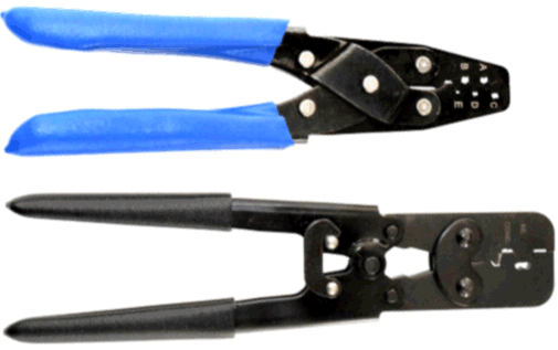
 FREE CRIMPER SET ($119 value) with purchase of RestoMod or Classic Update Wiring System.
 Frequently Asked Questions

Below are answers to many common questions our technical support staff receive. Use this material as a guideline to answer your questions or diagnose your vehicle’s electrical issues.
While we believe this information to be accurate and reliable, we cannot be held liable for its content. By using this information, you acknowledge that you do so at your own risk and accept full responsibility and liability for any damage to person or property that may occur as a result. This information may not be copied or duplicated in any form.
If you see a discrepancy with any information shown, please let us know.
About Our Products and What to Know Before Placing an Order.
How long was my original wiring harness designed to last?
Believe it or not, your car’s original wiring harness was only designed to last for 10-15 years! For those of you with cars from the 50s through the 80s and still using the original harnesses, you’ve surpassed the intended service life by 35-65 years!
When we hear people claim that the wiring in their 1950s, 60s or 70s car is still in ‘great shape,’ we must respectfully disagree. This isn’t just because we sell wiring harnesses.
It’s a matter of deterioration. There’s no effective way to completely seal off air and moisture from the strands in a wire. Moreover, most automotive wiring isn’t shielded from hydrocarbon contamination.
Most automotive wire is made of copper strands. Copper, being an active metal, reacts readily with oxygen, moisture, and pollutants. To understand this, just leave a polished copper kettle in your kitchen for a couple of months and see how it tarnishes. The same thing happens to automotive-grade copper wire.
Corrosion increases electrical resistance, which in turn generates heat and other electrical issues.
If your wiring has become brittle and cracked, especially evident in the high-heat engine compartment, it’s already in an advanced stage of deterioration and needs immediate replacement. At this stage, a short circuit to ground is imminent, which can even lead to a fire in the worst-case scenario.
Even if you find an N.O.S. (new old stock) wiring harness, the wire strands will have deteriorated over time just from sitting on a shelf, making it unwise to purchase one.
The same corrosion issues affect the metal terminals over time.
What are signs that my wiring must be replaced?
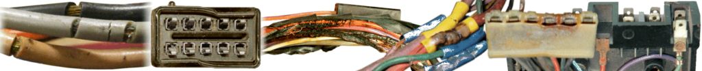
Does your wiring look like this?
- A – exposed wire core
- B – attempted splice “repairs” using poorly affixed, hand crimp connectors & clips
- C – using electrical tape to cover exposed copper wire
- D – burnt wiring caused by a short-to-ground
- E – exposed copper wire caused by flexing old, brittle insulation
- F – cut-off and missing terminals and connectors
- G – rusted fuse block terminals
- H – wires tapped into fuse block to circumvent a problem or to add an accessory
As we know from the FAQ question above, automotive wiring was not designed to last 40-70 years. Bad automotive wiring can lead to a range of problems, from minor inconveniences to major safety issues. Here are some signs to watch out for:
Flickering or Dimming Lights: If your headlights or interior lights flicker or dim, it could be a sign of poor connections or damaged wires.
Electrical Gremlins: If certain electrical components (like windows, locks, or gauges) work intermittently or don’t function at all, it might be due to faulty wiring.
Blown Fuses: Frequent blowing of fuses can indicate an underlying wiring problem. It’s often a sign that there’s a short circuit or an overload somewhere in the system.
Burning Smell: A burning odor from under the dashboard or in the engine bay can signal overheated wires or insulation, which could be a fire hazard.
Hot Wires: If you touch a wire and it feels unusually warm, it might be carrying more current than it should, which is a sign of potential wiring issues.
Corroded or Frayed Wires: Corrosion or visible fraying on wires can lead to poor connections and shorts. Look for any signs of wear or damage.
Erratic Behavior of Electrical Components: If components like the radio, air conditioning, or dashboard lights act erratically, it could be due to bad wiring or poor connections.
Warning Lights on Dashboard: Sometimes, malfunction indicator lights or other warning lights can come on due to electrical issues related to wiring.
Unusual Sounds: Clicking, popping, or buzzing noises from electrical components can indicate wiring issues.
Inconsistent Electrical Performance: If your car’s electrical system behaves unpredictably or you notice that certain components only work when the car is in specific conditions (e.g., engine on/off, parked/moving), it may be a sign of wiring problems.
If you notice any of these issues, it’s a good idea to have a professional mechanic or an automotive electrician inspect your vehicle’s wiring to diagnose and fix the problem. Better yet. Lectric Limited offers brand new wiring harnesses. Eliminate your car’s electrical problems, or potential problems, by replacing all the wiring with new harnesses from Lectric Limited!
Aren’t all wiring harnesses the same? Why should I buy from Lectric Limited?
While some companies offer ‘generic’ automotive wiring, Lectric Limited’s ‘Original Design Series‘ wiring harnesses are manufactured to the original factory blueprint specifications. These wiring harnesses are identical to those which were installed on your car when it left the factory. These harnesses are plug-and-play, designed for a straightforward connection to your vehicle.
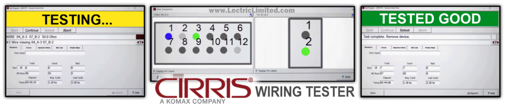
We also distinguish ourselves as an automotive wiring manufacturer that circuit-tests every harness we make, while it’s being manufactured, and before it leaves our facility. We use industry-leading Cirris Systems circuit testers, which are also used in the aviation industry, for testing wiring harnesses. Since wiring harnesses are assembled by people, sometimes errors can occur. This is one of the reasons why circuit testing is essential to guarantee that your harness operates flawlessly BEFORE installation. This system instantly tests hundreds of test points at each connector for continuity, mis-wires, missing wires, high-resistance, etc.
While many manufacturers offer warranties (as do we), you don’t want to face the hassle of removing a newly installed harness that wasn’t assembled correctly, nor do you want to risk potential fire hazards for poorly made wiring. Choose a harness that has already been circuit-tested so that you can be confident in a single, hassle-free installation.
I want to rewire my vehicle but don’t know if I should choose the Original Design Series™, RestoMod Series™, or Classic Update Series™ wiring.

Rewiring your show car, weekend driver, or daily driver can feel daunting, especially when you’re faced with the challenge of choosing the right wiring series and harnesses.
To help you make the best choice, please read this information. This information and the answers to a series of questions will guide you in the right direction, helping you to make the right decision.
Will your wiring be ready for me to install without having to cut wire, crimp terminals, tape the harness, etc.?

Yes. Our ‘Original Design Series‘ wiring harnesses are manufactured to the original factory blueprint specifications. These wiring harnesses are identical to those which were installed on your car when it left the factory. These harnesses are plug-and-play, designed for a straightforward connection to your vehicle.
In rare cases, we might not have access to the original connectors required for the harness. If this happens, you may need to use a connector from your old harness. However, we generally include a functional replacement connector with your new harness. While this replacement will work correctly and be electrically sound, it might not match the original if you’re concerned about vehicle judging.
We also recommend comparing the new harness with your original one before installation to ensure you have ordered the correct harness for your application.
Please note that our ‘RestoMod Series‘ and ‘Classic Update Series‘ wiring systems will require some assembly.
Do spark plug wires wear out?

Spark plug wires do wear out. With the exception of some high-performance applications, spark plug wires used on vehicles from the 1960s to the late 1980s are not made of traditional (solid) wire; they’re constructed from delicate carbon fibers (carbon core). Over time, these fibers break down and separate, leading to increased electrical resistance. High resistance diminishes the spark, resulting in poor combustion, misfires, and reduced fuel efficiency. If this issue persists, or if the insulation or boots are even slightly compromised, the wires may start leaking voltage to nearby engine components, causing arcing, performance issues, and even ignition component failures.
NOTE: If your vehicle requires carbon core (resistance) spark plug wires, continue to use them. Do not substitute them for solid core (very low resistance) wires thinking that they’re “better”, especially if your vehicle has an electronic ignition system. Vehicles from the early 1950s and prior did use solid core spark plug wires, but those ignition systems were designed for very low resistance wires.
It’s important to replace your spark plug wires before they wear out. We recommend changing them according to your owner’s manual, whenever you replace the spark plugs, or if you just want to freshen-up the look of your engine compartment. Lectric Limited manufactures both exact reproduction and replacement spark plug wires sets for many General Motors, Chrysler and AMC vehicles. See our online catalog for the spark plug wires originally used on your vehicle.
Can I buy factory-direct?

You sure can!
You can purchase directly from Lectric Limited or through one of our approved dealers—whichever option suits you best.
Lectric Limited provides free technical support both before and after your purchase. Just remember to always insist on Genuine Lectric Limited wiring & electrical products for your vehicle!
Will your Corvette wiring products pass the rigorous judging standards of the NCRS, Bloomington Gold Certification, MCACN Triple Diamond, and other Corvette judging certifications?

Absolutely!
99.99% of our reproduction (not replacement) products will meet the stringent judging standards for major awards in Corvette and Chevrolet categories, ensuring 100% accuracy!
However, if you have questions about our products, we encourage you to ask specific details, such as, “Are the wire colors in your harness identical to the original?” rather than broader questions like, “Will this pass NCRS?” or “The judge deducted points from my old harness—how does yours compare?” We have the original blueprints and expertise to guarantee authenticity in automotive wiring and electrical components.
Remember, car show judges are hobbyists who may only judge occasionally and can occasionally make errors. Wiring is our business!
Our strive for perfection, accuracy, and attention to detail has kept us in business for over 50 years.
Will your wiring products pass the judging standards of the major General Motors, Chrysler or AMC automotive awards?
Absolutely! Whether it be for Chevrolet, Buick, Oldsmobile, Pontiac, Cadillac, GMC, Chrysler, AMC or Jeep, 99% of our reproduction (not replacement) products will pass the rigorous judging standards of ALL the major automotive awards.
However, if you have questions about our products, we encourage you to ask specific details, such as, “Are the wire colors in your harness identical to the original?” rather than broader questions like, “Will this pass XYZ judging?” or “The judge deducted points from my old harness—how does yours compare?” We have the original blueprints and expertise to guarantee authenticity in automotive wiring and electrical components.
Remember, car show judges are hobbyists who may only judge occasionally and can occasionally make errors. Wiring is our business, not our hobby! Our strive for perfection, accuracy, and attention to detail has kept us in business for over 50 years.
My NCRS (National Corvette Restorer’s Society) judging manual state one thing, but your product description state another. Which is correct?
Although the N.C.R.S. judging reference manuals are very accurate and have been used for years at every Corvette judging event throughout the country, we believe that there are some discrepancies in what the NCRS manual states from what the original GM blueprints tell us; specifically in the areas of battery cable part numbers, scripting on spark plug wire, and spark plug wire boot colors.
The original GM blueprints that we use to make your Corvette wiring are the same as what GM used to make wiring installed on a car when it rolled off the assembly line.
So, to answer the question, we are correct! We have the documentation to validate this statement, and 50 years in the business will attest to this fact. Manufacturing accurate reproduction wiring is not our hobby, it’s our business.
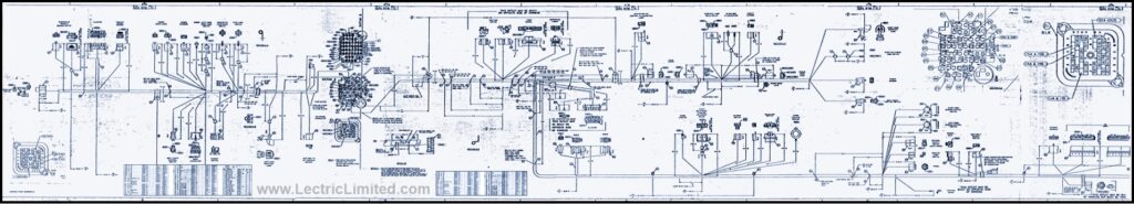
Do your products include installation instructions, schematics or wiring diagrams?
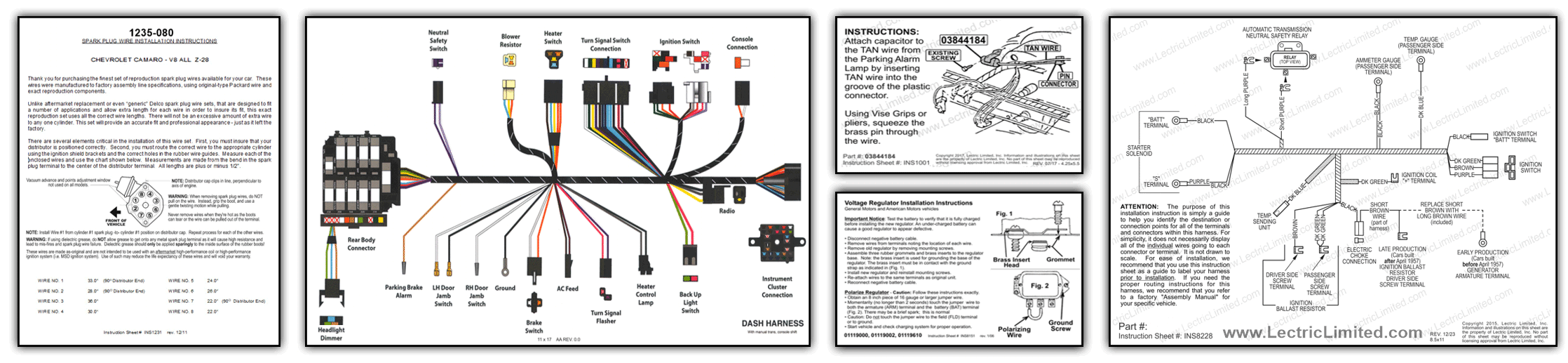
WIRING HARNESSES: All of our Corvette ‘Original Design Series‘ wiring harnesses include detailed installation instructions showing the connection for every wire and connector.
Many, but not all, of our non-Corvette ‘Original Design Series‘ wiring harnesses include installation instructions. If this information is included on the original blueprints, we included the instructions.
A few of our specialized harnesses and kits do include instructions. These include: 1947-1959 Chevy Truck Complete Wiring Sets, Camaro Console Gauge Conversion Harnesses, GTO Rally Gauge Adapter Harness, Corvette T.I. Ignition Module, all Alternator Conversion Harnesses and a few others.
In other situations, installation instructions, schematics and wiring diagrams are not included with our ‘Original Design Series‘ reproduction wiring harnesses, nor were they ever included with harnesses once available from dealers or a part’s store.
We suggest that you have a ‘Factory Assembly Manual’ on hand when installing your new harness. ‘Factory Assembly Manuals’ (if available for your year/make/model) contain general overview schematics, as well as line drawings of how to route the harnesses within your car. The Assembly Manual is what the factory assembly line workers used to properly route the wires – so they reach where they are supposed to. These Assembly Manuals are usually available from your restoration part’s supplier. (Note: A ‘Service’ or ‘Shop’ manual will usually not provide any information on harness routing). Another installation tip is to install your new harness at the same time you are removing your old harnesses – one step at a time.
FYI: We do sell laminated wiring diagrams for 53-82 Corvette. These are most beneficial when trying to troubleshoot an electrical problem but are not much use when installing a harness.
WIRING SYSTEMS: All of our ‘RestoMod Series’, ‘Classic Update Series‘ and ‘Custom Update Series’ wiring systems include installation instructions. Even scripted on the wires themselves are locations to where that circuit goes to (ex. the wires that go to the headlights would have ‘headlights’ scripted on the wire leads).
SPARK PLUG WIRE SETS: All of our spark plug wire sets include installation instructions showing wire lengths and corresponding cylinder numbers.
SWITCHES & ELECTRICAL DEVICES: Some, but not all, include installation instructions.
Does your dash harness include the fuse block?
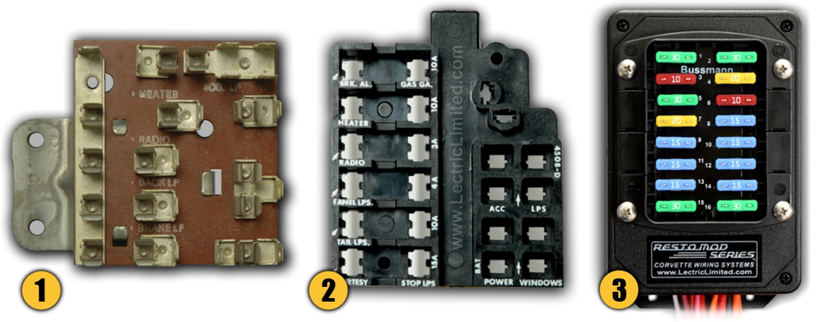
1 – If your vehicle’s fuse block/panel is made of the reddish-brown/tan fiber board material, used on many pre-1959 vehicles, then this fuse panel was not part of your original harness. It was a separate component. Consequently, we do not include the fuse block/panel with our Original Design Series™ dash harness or Custom Design Series™ truck harness for that vehicle.
2 – If your fuse block was of the type made with the black phenolic/bakelite material, this fuse blocks was originally part of, and integrated into, the dash harness. Consequently, we do include it* with our Original Design Series™ dash harness for that vehicle. (* Exceptions would be when we require a customer’s donor harness in order to re-use their original fuse block. This is not a common occurrence and only required when we are not able to obtain a new, reproduction fuse block. See FAQ question about donor-required harnesses.)
3 – All of our Custom Update Series™ and RestoMod Series™ wiring systems come with an ATO-type fuse block. Fuses included.
What type of fuses are used in your fuse block?
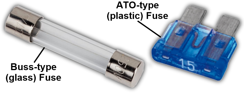
GM vehicles from 1958 to 1978 originally used a Buss-style fuse block with Buss-type (glass) fuses. Our Original Design Series™ wiring harnesses include this Buss-type fuse block with all of our 1958-1978 dash harnesses unless otherwise noted in our catalog.
GM vehicles from 1979 and later originally used an ATO-type fuse block with ATO-type (plastic, blade-type) fuses. Our Original Design Series™ wiring harnesses include this ATO-type fuse block with all of our 1979 and later dash harnesses unless otherwise noted in our catalog.
All of our Custom Update Series™ and RestoMod Series™ wiring systems use an ATO-type fuse block with ATO-type (plastic) fuses. We include this ATO-style fuse block all of our Custom Update Series™ and RestoMod Series™ wiring systems.
There is a common misconception that the newer ATO-type (plastic) fuses are safer than the older Buss-type (glass) fuses. This is not true. Provided that you use the correct amperage rated fuse in your fuse block, the Buss-type are as safe as the ATO-type. One of the main reasons that automotive manufacturers switched from Buss to ATO fuses is that ATO fuses are smaller and more compact, allowing manufacturers to design more efficient fuse boxes with more circuits in a smaller space. This was required for more modern vehicles with increasingly complex electrical systems.
What type of wire do you use in your wiring harnesses?
Lectric Limited manufactures all of its wiring harnesses with the same type of wire as specified by the original equipment manufacturers (OEM) blueprint specifications, or an upgraded substitute. We source all our wire from USA wire mills. With the exception of some specialty wire (example, resistance wire, fusible link wire, etc.) all of the wiring we use is made with a pure-copper core, and all of the wire’s insulation is petroleum-based, either GPT, GXL or SXL. Lectric Limited does NOT use inferior, rodent-attracting wire with soy-based insulation.

PETROLEUM-BASED INSULATION (Use by Lectric Limited): Traditional automotive wire insulation was made from petroleum-derived plastics, such as PVC or polyethylene. These materials are less biodegradable, chemically inert, and often contain additives that can make them less attractive to rodents.
Overall, petroleum-based insulation has a proven track record of resisting rodent activity, making it more reliable for long-term durability in environments where rodents are present—such as rural areas, barns, or garages.
SOY-BASED INSULATION: In recent years, automakers have increasingly turned to cheaper, more “eco-friendly” materials, including soy-based insulation for automotive wiring. While this wire is more environmentally friendly, it has unintentionally introduced a practical issue: increased rodent damage. Soy, being an edible material, has been effective at attracting rodents of all kinds to then chew on the vehicle’s wiring, especially during the cold weather months. As you can imagine, this can cause serious problems, like causing short-circuiting or entire electrical and electronic systems to fail, alongside thousands of dollars in damages.
Why do you sometimes require a ‘donor harness’?
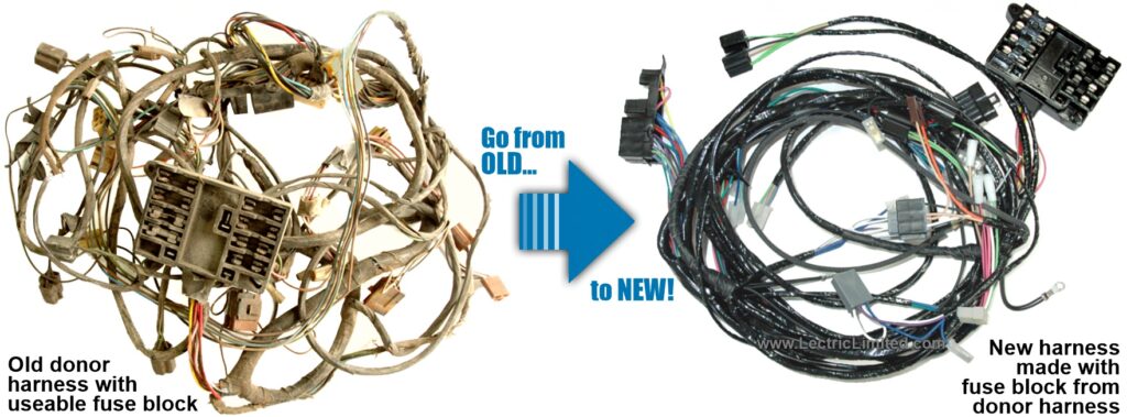
What do we mean by a ‘donor harness’ ? A donor harness is sometimes required when we lack specific components needed to manufacture your new, reproduction wiring harness. These components are no longer available and no longer being reproduced, making it impossible to manufacture your new harness without them. In our online catalog, if there is a notation that “…customer must provide a useable (component) “, this means that we will need to use one or more components from your old (donor) harness to manufacture your new wiring harness. Of course, the remainder of the components (wire, terminals, connectors, clips, tape, etc.) will all be new when you receive your manufactured harness.
What do we NOT mean by a ‘donor harness’ ? We only build wiring harnesses from the original manufacturer’s blueprint specifications. We do not build wiring harnesses from customer’s sample harnesses. For this reason, if the harness you need is not offered in our online catalog, we would not be able to manufacture it, even if you send us your old harness.
What components do we require from your donor harness? The required components are usually listed in the online catalog description. They can be a fuse block, bulkhead connector (the bulkhead connector is the one that goes through the firewall), or a unique component. These components must be useable and not broken.
How often is a donor harness (or donor components) required? Not very often. Only about 2% of the wiring harnesses we offer, require that you first provide us with components from a donor harness. See list below.

What should you do (and not do) if a donor harness is required? If we require your ‘donor harness’ before we can make your new wiring harness, for fastest service, please phone-in your order. Do not order online. We will discuss the process with you and issue an RMA# for the donor harness.
Important: If you need to send us components from a donor harness, we strongly recommend sending the entire harness instead of cutting off the components yourself. Customers have sometimes damaged parts during removal. In addition, sometimes components were needed that weren’t originally specified, resulting in a manufacturing delay and multiple shipping charges incurred by the customer.
What if you don’t have a donor harness to send? We recommend that you search on eBay, internet automotive forums/clubs, automotive swap meets, or salvage yards for the harness or components you’ll need. Make certain that the components are useable and not broken. We do not have any donor harnesses or donor components to provide. Unless noted in our online catalog, we will not make a ‘donor required’ harness without the required components.
What will we do with your donor components? Upon initial inspection, if it is determined that the component required to make your new harness is in good condition, not broken or about to break, our technicians will carefully remove the component with the proper tools. Upon manufacturing your new harness, if a fuse block was used from your donor harness, we will replace all the fuse clips and terminals within the fuse block with new ones. If a connector was used from your donor harness, we will replace all the metal terminals with new ones.
Disclaimer – Please Note and Completely Understand: Donor-required harnesses are considered a ‘special order’ item and are non-returnable and non-refundable. If it is determined later that we cannot use the component(s) from your donor harness, even if we initially believed we could, we will be unable to manufacture your harness. In such cases, we will notify you and return the non-usable component(s) and donor harness to you.
Please note that 50-70 year old plastic wiring components have degraded and could break during shipping, removal, or assembly. While we take great care handling donor harnesses, we are not responsible for any issues or damages related to the condition or usability of the donor harness components, including any inability to manufacture your new harness or any effects on your vehicle’s operability. This means that in some cases, not only will we be unable to produce your new harness, but damaged or removed components (such as cut wires, terminals, or connectors) from your donor harness could render your vehicle inoperable! Although rare, this is a possibility, and we advise you to carefully consider this before placing your order for a ‘donor required’ harness.
PLEASE NOTE: If your vehicle and the desired wiring harness is listed below, do NOT place your order online. Instead, phone-in your order (708-563-0400) to avoid delays and to make sure your order is processed correctly. At that time, we will also issue you an RMA# to receive your donor harness.
Harness purchases that require us to first receive a ‘donor harness’ before we can manufacture your new harness include (but not limited to) our Original Design Series™ :
- Buick Full-Size Power Window Harness
- Buick Skylark/Special (1964-67) Dash Harness
- Buick Skylark/Special Power Window Harness
- Cadillac Dash Harness
- Chevrolet Camaro (1981) Dash Harness
- Chevrolet Chevelle/Monte Carlo/El Camino Power Window Harness
- Chevrolet Full-Size (1963) Dash Harness
- Chevrolet Full-Size Power Window Harness
- Chevrolet Truck/Pick-Up/Suburban/Blazer (1973-74) Dash Harness
- Oldsmobile Cutlass/F85 (1964-67) Dash Harness
- Oldsmobile Cutlass/F85 Power Window Harness
- Oldsmobile Full-Size (1958) Main Harness
- Pontiac Firebird/Trans Am (1981) Dash Harness
- Pontiac Full-Size (1955-62) Dash Harness
- Pontiac Full-Size (1964-67) Engine Harness
- Pontiac Full-Size (1964-67) Front Light Harness
- Pontiac Full-Size Power Window Harness
- Pontiac GTO/Le Mans/Tempest Power Window Harness
Can you refurbish / restore my existing wiring harness?
We do not refurbish old wiring. We only manufacture brand new wiring harnesses.
We do not recommend “refurbishing” old wiring harnesses as many times the wire and terminals have oxidized (leading to high resistance) and the plastic connectors have probably deteriorated.
Do you keep wiring products in stock?

We stock, and have ready to ship, 99% of our Corvette Original Design Series™ wiring, Corvette RestoMod Series™ wiring systems and 1955-57 Chevrolet full-size Original Design Series™ wiring.
For other year/make/model vehicles, the harnesses will most likely need to be manufactured. Due to the numerous variations, even within the same year/make/model, it’s not feasible to stock every option. Turn-around time for non-stock wiring harnesses is about 2-3 weeks – slightly longer during peak season. Turn-around time for non-stock spark plug wire sets is only a few days.
We operate on a ‘fair to every customer’ queue basis. So, whether you’re a first-time customer ordering only one wiring harness or you’re our largest dealer placing a very large order, all orders will be processed and completed in the order it was received. For this reason, we do not offer an express manufacturing service.
What Do I Need To Buy?
I need the Corvette harness that wires my (specific component), but I’m not sure which harness to buy.
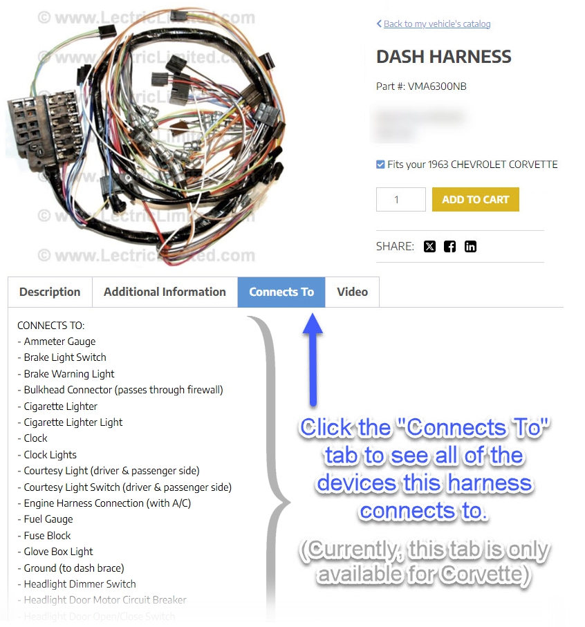
Many times, customers call us to ask, “What harness do I need that goes from ‘here’ to ‘there’?” or “What harness connects to (for example) the alternator?” or “What harness connects to (for example) the windshield wiper motor?” For your convenience, on all of our 1953-82 Corvette wiring harness, we display a “Connects To” tab. Clicking this tab will display all of the components that specific harness connects to.
In addition to our “Connects To” tab, we also have a ‘What Corvette Harness Goes Where?’‘ chart. This chart will help you determine the specific harness you might need to correct an electrical problem in your 1953-67 Corvette.
This chart should help you determine the specific harness, harnesses, or lead wires you might need to either re-wire an entire area of your Corvette (ex. the entire under-hood wiring), or to re-wire a specific component (ex. the starter motor).
As you will see, some harnesses route to different sections of the car (ex. the dash harness runs from the passenger compartment into the under-hood area; wiring components within both those areas).
What harness connects to my charging system (generator/alternator, voltage regulator, etc.)?
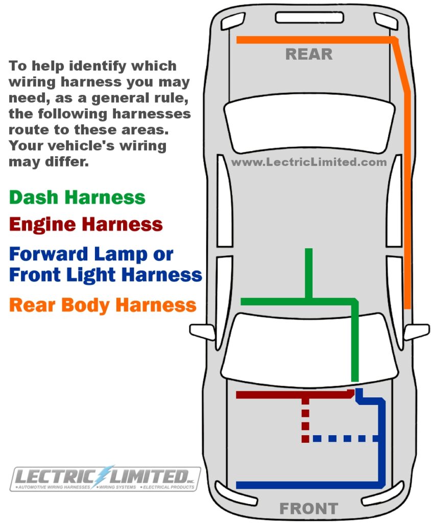
As a general rule:
The Engine Harness runs from the firewall connector, along the upper part of the firewall, below the windshield.
The Forward Lamp Harness runs from the firewall connector, along the driver’s side fender, to the front of the vehicle.
First, identify the wiring that goes to the generator/alternator and trace it back. If the generator/alternator wiring connects to the harness that runs along the firewall (under the windshield), then you will need the Engine Harness. If the alternator wiring connects to the harness that runs along the driver’s side fender, then you need the Forward Lamp Harness.
For Corvettes:
- From 1953-57 the charging system wiring of a Corvette was incorporated into the Dash Harness.
- From 1958-62 the charging system wiring of a Corvette was incorporated into the Dash Harness, Engine Harness, and Regulator to Generator Harness.
- From 1963-67 the charging system wiring of a Corvette was incorporated into the Engine Harness.
- From 1968 & up, the charging system wiring was incorporated into the Forward Lamp Harness. Keep this in mind when ordering a harness to correct a charging problem.
- (also see the FAQ answer above)
Explain the Corvette T.I. (transistor ignition) components. What do I need to buy?
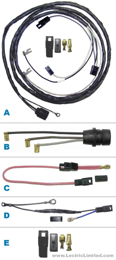
If you want to replace all the wiring for your 1964-71 Corvette’s T.I. (transistorized ignition) system, you will need to buy:
- A) Auxiliary Harness,
- B) Amplifier Box Extension,
- C) Extension Wire (1968-71 Corvettes),
- D) Voltage Regulator Adapter Harness (1965 Corvettes).
Below is a brief explanation of these components.
A) T.I. AUXILIARY HARNESS
This is the main wiring that goes from the distributor to the T.I. amplifier box. On Corvettes, this harness mates to the wires coming from the rubber molded connector (or from the rubber molded pigtail) coming from the T.I. Amplifier Box.
This T.I. Auxiliary Harness includes the resistance wire and the conversion kit. The conversion kit is necessary to convert one of our new engine harnesses to accept this T.I. harness. If your car already has an engine harness that was factory-converted to accept the T.I. harness, and your harness has not been modified or repaired since, then you won’t need to use the conversion kit. The conversion kit can be discarded or saved for possible future use. (It is up to you, or your mechanic, to determine if your harness has been previously modified or repaired.)
B) T.I. AMPLIFIER BOX EXTENSION
This is the wiring from the internal circuit board that includes the rubber molded T.I. Amplifier Box housing connector -to- the T.I. Auxiliary Harnesses molded rubber connector. Basically, it is the wiring that is part of the amplifier box. This is the weakest link in the T.I. system and must be replaced if you have not already done so. Over the years, the spring-tension on the female terminals of this wiring WILL lose their ‘grip’ on the male terminals they connect to, causing your engine to quit.
C) T.I. EXTENSION WIRE
Used only on 1968-71 Corvettes, this is the wire that goes from the ignition switch, through the firewall, to the T.I. Auxiliary Harness.
D) T.I. VOLTAGE REGULATOR ADAPTER HARNESS
Used on 1965 Corvettes only, this harness is used to filter-out ignition noise caused from the engine harness. Without this Adapter Harness, noise induced into the T.I. harness from the Engine Harness could cause your engine to misfire. This harness contains a noise canceling diode. The actual application of this harness is vague. No documentation is available as to whether it’s used on a big block, small block or both. However, we do sell this harness (# VVR6500A).
E) T.I. CONVERSION KIT
We offer this conversion kit because some dealers do not include this kit as part of the T.I. Auxiliary Harness (We do!). This kit includes all terminals, connectors & instructions as used by the factory to install T.I. This kit is not necessary if your 1964-71 Engine Harness and 1964-67 Dash Harness have already been converted to accept T.I. This kit is also not necessary if you purchase a Lectric Limited T.I. Auxiliary Harness directly from us, since we include the conversion kit.
————————————–
Other T.I. items we carry:
T.I. AMPLIFIER BOX UPDATE MODULE

This is a solid-state T.I. module that replaces the original circuit board. It fits completely inside your amplifier box making it undistinguishable from original. It is a simple screw-in replacement. We offer this module for 1964-71 Corvettes.
Did you know that many times a problem with an original T.I. system can be traced back to the electronic components. Many years ago, when the T.I. system was developed, Germanium transistors were ‘state-of-the-art’ in electronic technology. This type of transistor, however, had many limitations and many amplifier failures can be traced back to these transistors. Our VTR6571AM replacement module uses the newer-type Silicone transistors that rarely fail. Other problems that led to amplifier failure were due to water from a faulty cover seal. Moisture trapped inside the amplifier box will cause corrosion to the extent it will rust electrical component leads and destroy copper tracks (traces) on the printed circuit board, thus leading to failure. All of the electronic components in our module are completely encapsulated/sealed. If water does get trapped inside your box, the module will not be affected.
NOTE: Transistorized ignition is a very specialized performance option that works well, when it works. When it doesn’t, it can be very frustrating. From an originality standpoint, if your car was originally equipped with T.I., you would want to retain the T.I. system.
If you are thinking of converting your car from OEM standard (non-electronic) ignition to T.I., don’t do it! Use our Breakerless-SE Electronic Ignition Conversion Kit (#38131) instead. The Breakerless-SE will be a cheaper, much easier to install, much more reliable, and a better alternative to T.I.
How do I convert my harness when switching from an externally regulated to an internally regulated alternator?
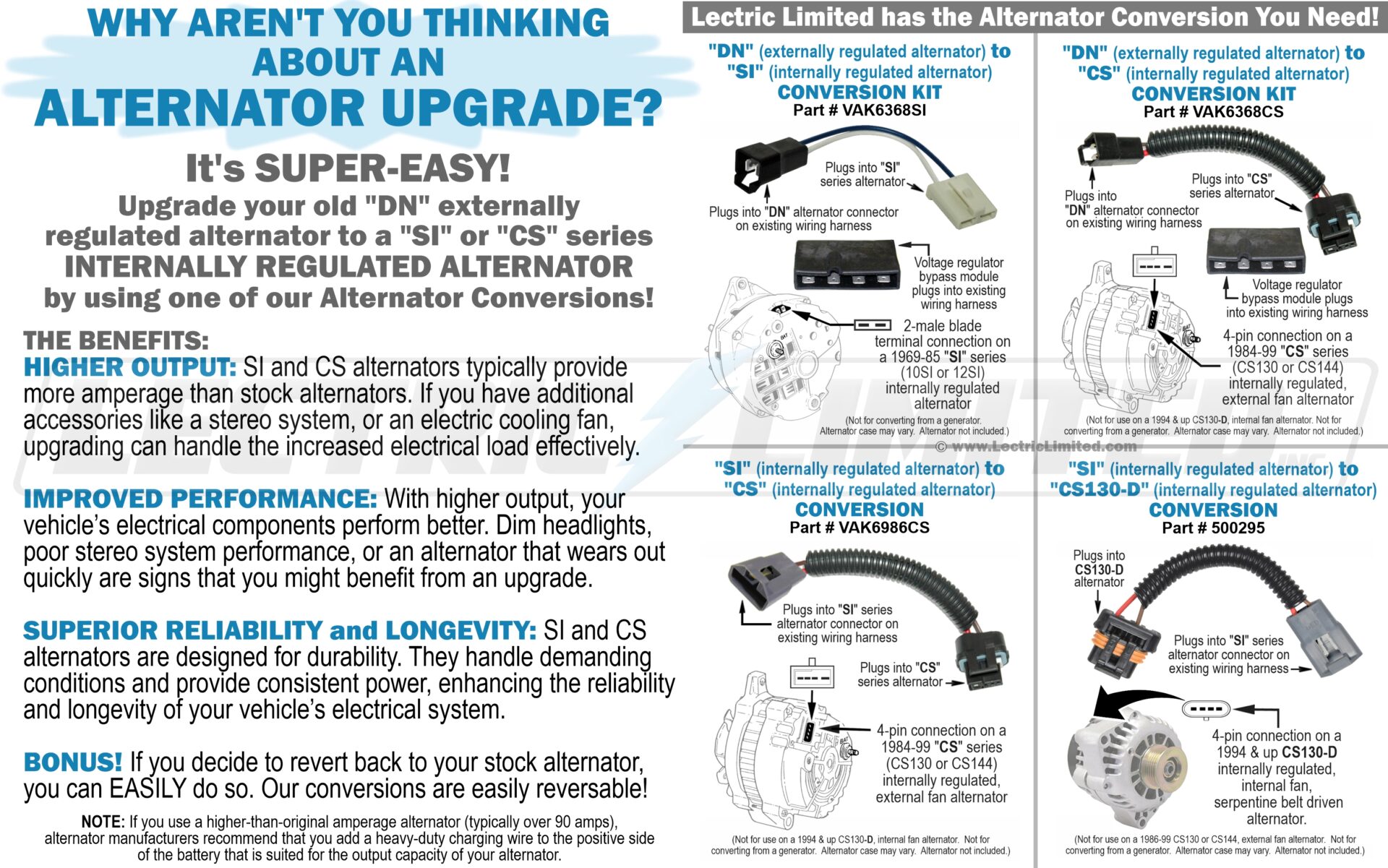
The problem when converting from an externally to an internally regulated alternator is adapting your original harness. Not only do you need to make sure the alternator will still charge the battery, but you’ll want to make sure your gauge or warning light is still able to alert you when the system is not charging.
Our recommendation on internally regulated alternators is to use a genuine Delco SI or CS type for all applications.
Lectric Limited offers an easy and inexpensive solution if you want to convert your wiring from an externally regulated alternator to an SI or CS type, internally regulated alternator, by using one of our Alternator Conversion Harnesses. See our online catalog to see if a conversion harness is available for your vehicle.
F.A.Q. on Internally Regulated Alternators:
The most common alternator ever produced is the 10SI (Systems Integrated), with the 12SI being an upgraded version by means of better cooling (noted by a plastic fan) to handle higher current outputs. The 15SI and 17SI are physically larger units.
Delco 10SI Series, 61 Amp, 12 Volt, CW, 1-Groove Pulley
Used On: (1985-73) Buick, Cadillac, Chevrolet, GMC, Olds., Pontiac 4, 6, 8 Cyl. Replaces: Delco 1105360
Delco 12SI Series, 78 Amp, 12 Volt, CW, 1-Groove Pulley
Used On: 1989-83 Buick, Cadillac, Chevrolet, GMC, Olds., Pontiac 4, 6, 8 Cyl. Replaces: Delco 1100250, 1105370, 1105372 & others
Delco 12SI Series, 94 Amp, 12 Volt, CW, 1-Groove Pulley
Used On: (1987-84) Buick, Cadillac, Chevrolet, GMC, Olds., Pontiac 4, 6, 8 Cyl. Replaces: Delco 1101308
The latest series of alternators to be introduced is the CS (Charging System) 130 or 144 (for 130mm or 144mm stator).
Delco CS130 Series, 100-105 Amp, 12 Volt, CW, 1-Groove Pulley Used On:
- (1990-88) Buick Estate Wagon 5.0L
- (1990-88) Cadillac Fleetwood Brougham (RWD) 5.0L
- (1990-88) Chevrolet Caprice 5.0L
- (1990-88) Oldsmobile Custom Cruiser 5.0L
- (1989-88) Pontiac Safari Wagon 5.0L
- Replaces: Delco 1101229, 1101275, 1101292
Delco CS144 Series, 140 Amp, 12 Volt, CW, 6-Groove Pulley
Used On:
- (1996-94) Buick Roadmaster 5.7L
- (1996-93) Cadillac Fleetwood Brougham (RWD) 5.7L
- (1996-93) Chevrolet Caprice 4.3L, 5.7L
- (1996-95) Chevrolet Impala 5.7L
- (1995-92) Chevrolet Lumina APV Van 3.8L
- (1995-92) Oldsmobile Silhouette 3.8L
- (1995-92) Pontiac Trans Sport 3.8L
- Replaces: Delco 10479891, 10480201
You sell a 1963 Corvette Headlight Bucket Extension Harness for cars with fiberglass buckets or cars with metal buckets. Which one do I need?
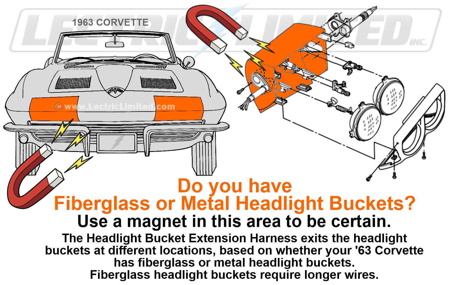
All 1963 Corvette headlight buckets were originally made of fiberglass. So, our headlight bucket extension harness, designed for use with fiberglass headlight buckets (part # VHX6300), is correct.
However, if a fiberglass headlight bucket got damaged and needed replacing, the only available option was a replacement headlight bucket made of metal. And through the years, many of the original 1963 Corvette fiberglass headlight buckets were replaced with the metal ones. Consequently, the wiring had to be changed.
We offer a VHX6367 Headlight Bucket Extension Harness for those 1963 Corvettes that have the newer, metal buckets.
If you are not sure if you have a fiberglass or metal headlight bucket, put a magnet to it!
What cars will your T-3 sealed beam headlight bulbs fit?
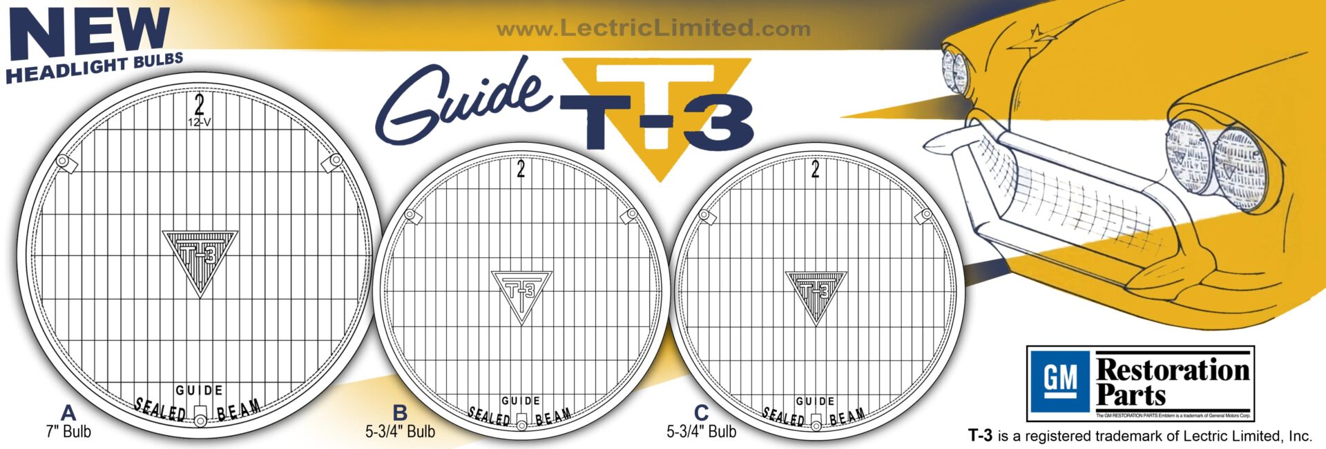
A) Part # SB6169S will fit, and be correct for, all 1959-69 (and some 1970) GM vehicles with a (2) 7″ round headlight bulb system. Complete set includes (2) hi-low beam 7″ bulbs.
B) Part # SB6067S will fit, and be correct for, all 1960-67 GM vehicles with a (4) 5-3/4″ headlight bulb system. Complete set includes (2) hi-low beam & (2) hi beam 5-3/4″ bulbs.
C) Part # SB6871S will fit, and be correct for, all 1968-71 GM vehicles with a (4) 5-3/4″ headlight bulb system. Complete set includes (2) hi-low beam & (2) hi beam 5-3/4″ bulbs.
D) Part # SB6871HS (not shown) will fit, and be correct for, all 1968-69 Oldsmobile Toronado. Complete set includes (2) hi-low beam 5-3/4″ bulbs.
I want to install aftermarket air-conditioning, like VintageAir™. Should I buy my wiring harnesses for a car with or without factory air-conditioning?
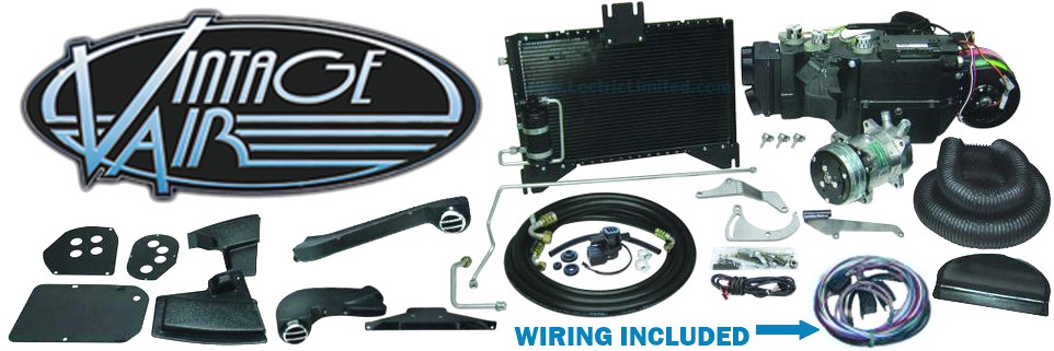
If you plan to purchase our Original Design Series™ wiring harnesses, and want to install VintageAir™ aftermarket air-conditioning, we recommend that you buy your wiring harnesses for a NON-A/C vehicle. VintageAir™ is an independent air-conditioning system that only requires a keyed hot power source, a main power source from the battery, and a ground. All of the wiring that is required for the installation of the VintageAir™ system will be included with that system. Meaning, if you inadvertently purchased the air-conditioning wiring harness for factory installed A/C, you will not use any part of that wiring harness when installing a VintageAir™ system.
If you plan to purchase our RestoMod Series™ or Custom Update Series™ wiring system, those systems can be used with or without VintageAir™ (aftermarket) air-conditioning.
What is C.A.C. A/C, Comfortron A/C, Circ-L-Aire A/C, CoolPack A/C, Option Code 60/65/75, etc. in reference to GM air-conditioning wiring harnesses?
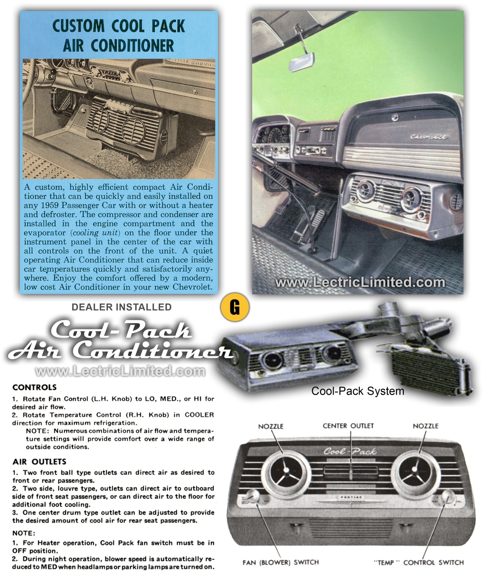
Some of the GM wiring harness we offer reference options like: with A/C, with C.A.C. A/C, with Cool Pack A/C, option code 60, option code 65, option code 75, etc. But what do these accessories/options mean and where do I find them?
A list of all possible RPO (Regular Production Option) Codes for a specific year and model is available.
These options/accessories are typically listed in an accessories’ brochure and the factory assembly manual for that year/make/model. To ensure you order the correct wiring for your vehicle based on these options, refer to this information.
Cars of this era were manufactured with:
- A/C – optional factory installed air-conditioning only.
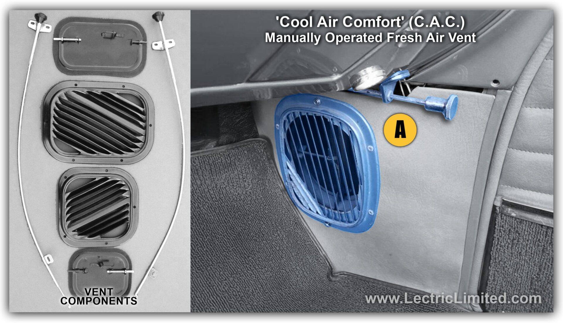
- C.A.C. – ‘Cool Air Comfort’, manual cable control, fresh air ventilation only. There is no wiring.
- C.A.C. A/C – ‘Cool Air Comfort’ & optional factory installed air-conditioning.
- Comfortron A/C – optional (usually) factory installed auto temp./climate control air-conditioning.
- Circ-L-Aire A/C – optional (usually) factory installed auto temp./climate control air-conditioning.
- Cool-Pack A/C – optional dealer installed under dash air-conditioning unit.
GM RPO (Regular Production Option) Codes as they relate to air-conditioning options:
- C60 – air conditioner, front, manual controls
- C61 – air conditioner, front, automatic controls
- C62 – HVAC provisions auxiliary A/C compressor
- C62 – air conditioner, front installed, floor mounted
- C63 – HVAC system air conditioner, front & rear, auto & auxiliary temperature control, tri-zone
- C64 – HVAC system air conditioner, hang-on type
- C65 – HVAC system air conditioner, front, manual controls, without heater core
- C66 – air conditioner, HVAC, dealer to install condenser (not furnished)
- C67 – air conditioner, single-zone
- C67 – air conditioner, single-zone electronic
- C67 – air conditioner, front, electronic controls
- C68 – air conditioner, single-zone automatic climate control
- C68 – air conditioner, automatic climate control
- C68 – air conditioner, front, automatic, electronic controls
- C69 – air conditioner, rear
- C69 – air conditioner, rear auxiliary
- C75 – air conditioner, automatic temperature control
Referring to images (on the right):
A – C.A.C. is ‘Cool Air Comfort’ fresh air ventilation only. This ventilation system used a manually operated slider cable to open/close a ventilation door near the floorboard. There is no wiring involved with C.A.C. only cars. C.A.C. could either be ordered separately without A/C, or it came automatically installed on any factory-installed A/C car.
Image not shown – C.A.C. A/C means C.A.C. + optional factory-installed ‘BASIC’ air-conditioning. ‘Basic’ A/C means that it is not a user-settable temperature / climate controlled A/C like the trade named Comfortron, Circ-L-Aire, and other systems. Lectric Limited offers wiring harnesses for some cars ‘with c.a.c. a/c’. See our online catalog.
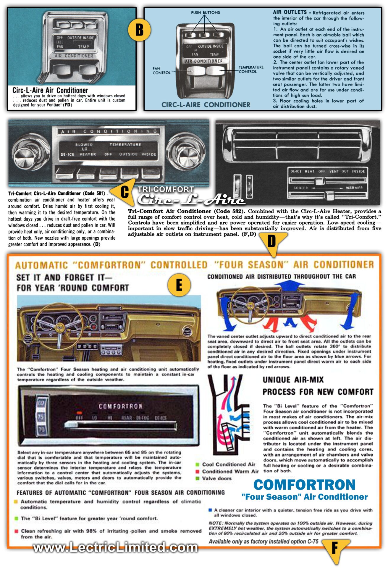
B – Circ-L-Aire A/C, a user-settable temperature/climate control A/C system, was only installed on GM full-size cars and was a rare option. Lectric Limited offers wiring harnesses some cars ‘with circ-l-aire a/c’. See our online catalog.
C – ‘Code 581′ in the accessories’ brochure for this year/make/model (in this instance, 1964 Wide-Track Pontiac Accessories) was the sales code # for ‘Air Conditioner Tri-Comfort’. The GM RPO Code was C60.
D – Code ‘F D’ in the accessories’ brochure for this year/make/model (in this instance, 1965 Pontiac Accessories), meant that this accessory could either be Factory or Dealer installed.
E – Comfortron A/C, a user-settable temperature/climate control A/C system, was only installed on GM full-size cars and was a rare option. Lectric Limited offers wiring harnesses some cars ‘with comfortron a/c’. See our online catalog.
F – Code ‘C-75′ in the accessories’ brochure for this year/make/model is the GM RPO (Regular Production Option) Code. In this instance, C-75 meant ‘air conditioner, automatic temperature control’. Lectric Limited offers wiring harnesses for some cars ‘with c75 a/c’. See our online catalog.
G – Cool Pack A/C, optional under dash air-conditioning unit, usually dealer installed. Lectric Limited does not manufacture the wiring for the Cool Pack A/C system itself. However, if you have this A/C system, you can buy the Lectric Limited wiring for a non-A/C car, and re-use your original wiring from the dealer-installed A/C.
What do you mean by ‘sweep style’ speedometer?
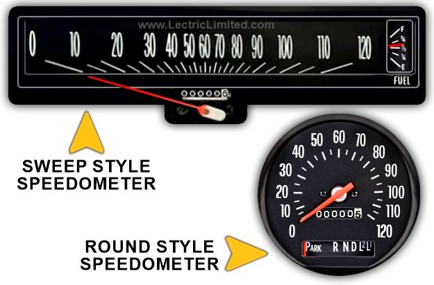
For some of our wiring harnesses, there is a difference in the harness if your car has the sweep style or round speedometer, as both could have been available for the same year/make/model car.
How can you the difference? A sweep style speedometer is a type of speedometer where the needle moves in an arc or a sweeping motion across the dial to indicate speed. Unlike a circular or full-round speedometer where the needle rotates around a central point, a sweep speedometer typically covers a horizontal or semi-circular range.
This design was popular in many vintage cars and is known for its aesthetic appeal and easy-to-read layout. The sweep motion makes it easier to glance at and gauge speed quickly, which is why it was commonly used in classic cars from the 1950s to 1970s.
I want to change my breaker-point ignition to H.E.I. What do I need to buy?
First of all, now it’s not necessary to replace your distributor if you want electronic ignition! Install our Breakerless-SE Conversion Kit (part #38131) and your worries are over.
Getting back to the question…All original ‘point type’ distributors require no more than 9.6 volts (approximately) to operate correctly. Most GM cars use a ‘white cloth covered’ resistance wire or a ‘ballast resistor’ to reduce the line voltage to the coil from 13.7 volts (approximately, when vehicle is running) to the necessary 9.6 volts (approximately). The ‘white cloth covered’ resistance wire or a lead from a ‘ballast resistor’ must not be used to power a GM H.E.I. distributor. This is a common mistake, that will degrade the performance of the ignition system. All GM H.E.I. distributors require full system voltage of 13.7 volts (approximately, when vehicle is running) to operate properly.
If you want to change your breaker-point ignition to H.E.I., we offer an HEI conversion service on some of our ‘Original Design Series’ wiring harnesses where we will correctly modify your harness from its original breaker-point application to a General Motors HEI distributor, while your harness is being built. See our online catalog for your application.
For 1969-84 Corvettes, we offer an HEI conversion wire (part #VIG6974HEI). This will allow you to replace both the resistance wire and starter solenoid-to-coil wire. To install a GM H.E.I. distributor, an ignition system crank/start resistance by-pass is required.
How do I convert my dashboard instruments from warning lights to gauges?
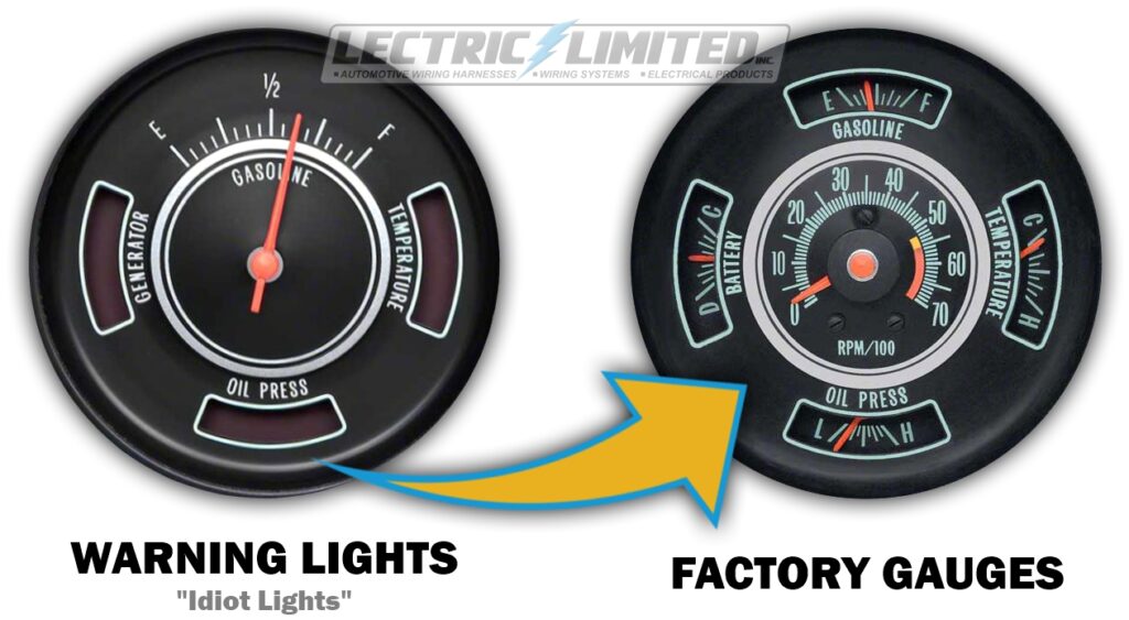
The two most popular models to convert from warning lights to factory gauges are 1967-69 Camaros and 1970-72 Chevelles/El Caminos. Note: Factory schematics for gauge type cars are not available, and were never produced by GM.
- 1967-69 Camaros:
The preferred and easiest method of converting a Camaro from warning lights to gauges, is to replace the Dash Harness, Forward Lamp Harness, Engine Harness and the Console Harness with harnesses manufactured for cars with gauges, which we offer. See our online catalog for your application. - 1970 & up Camaros:
You would need to buy and replace your Dash Harness, Instrument Cluster Harness (if applicable), Engine Harness (if applicable) and a Forward Lamp Harness (if applicable). See our online catalog for your application. - 1970-72 Chevelle / El Camino:
All 1970-72 Chevelles require replacement of the Dash Harness to a gauge style harness. 1970-71 models also require replacement of the Forward Lamp Harness to a gauge style. In addition, 1972 models require replacement of the Engine Harness to a harness manufactured for cars with gauges, which we offer. See our online catalog for your application.
1970 Corvette – What Dash Harness do I buy?
In the 1970 production year, G.M. used four different Dash Harnesses on Corvettes. Two were designed for cars with factory-installed air conditioning (1st and 2nd Design), and two for cars without factory A/C (also 1st and 2nd Design). It’s important to order the correct harness for your specific application.
Do I need to buy a 1st or 2nd design dash harness?
- If your Corvette still has its original Dash Harness, check how the harness is routed behind the speedometer and tachometer.
- If the harness has been removed, look for the location of the mounting brackets—either above or below the speedometer and tachometer.
- If the brackets are also missing, check for telltale signs such as screw holes showing where the brackets were originally installed.
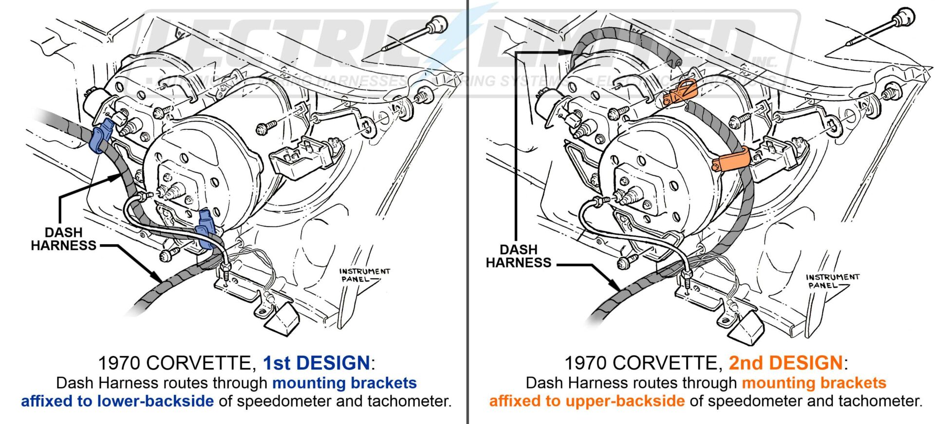
- 1970 Corvette – 1st Design:
The Dash Harness routes through the mounting brackets affixed to the lower-backside of the speedometer and tachometer. Order Dash Harness #VMA7000AC (with factory installed A/C) or VMA7000NA (without factory installed A/C). - 1970 Corvette – 2nd Design:
On very late build ’70 Corvettes, the Dash Harness may route through the mounting brackets affixed to the upper-backside of the speedometer and tachometer. Order Dash Harness #VMA7000ACL (with factory installed A/C) or VMA7000NAL (without factory installed A/C).
A common question is, “Can’t I just buy the ‘longer’ harness and it should work for both 1st or 2nd design installs?” No. Not only are there differences in wire lengths, but there are differences in break-out locations and wire lengths at those locations. Be certain to order the correct harness for your application.
What is the difference between the 1967-69 Delco/Guide and Boyne (type) turn signal switch?
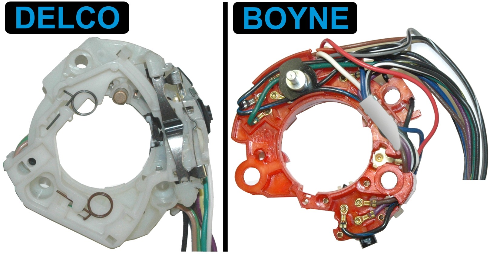
Both the Delco/Guide and Boyne-type turn signal switches were used on early GM cars (except Corvette). These two switches are physically different, and not interchangeable. When replacing your turn signal switch, make certain that you first identify your original switch. The Delco/Guide switch will have either of 3 words molded into the switch: ‘Delco Guide’, or ‘Delco’, or ‘Guide’. The Boyne switch will have ‘BPC’ molded into the switch.
After you identify the switch you have, you can then purchase the identical replacement. Currently, we carry both types. If you do not have original-type switch in your car, you would need to research your vehicle to determine the switch you need. We are not able to identify the switch for you.
Questions Before Installation
What should I do when I receive my new wiring harness?
IMPORTANT: Please ensure that the wiring harness you ordered matches the year, make, model, and application for your vehicle. We cannot accept returns on items that have been installed or attempted to be installed.
All our harnesses are guaranteed to fit and function properly for their intended application. Do not cut, modify, alter, or remove any tape or conduit without consulting us first.

ASSEMBLER TAG: Every Lectric Limited wiring harness has a white assembler/manufacturing tag on it. This tag identifies the harness to us for tracking, troubleshooting, quality control, and warranty issues.
Before installation, verify that the part number on the tag matches the part number on the bag, and confirm that this is the correct harness for your needs. Please note that our dealers may repackage our products and/or use a different part number on their website/catalog/invoice.
This tag also indicates that the harness has been thoroughly inspected before shipment. If there are any discrepancies, notify us or your dealer within 48 hours!
We highly recommend that you leave this assembler tag on. However, if you must remove it, please do so after the harness is fully installed, working properly, and you don’t foresee future technical questions about the harness.
INSTALLATION INSTRUCTIONS: See FAQ question below.
Why does the Lectric Limited harness I received appear slightly different than my original harness (or the schematics)?
Don’t worry. Your new harness was built correctly. Every Lectric Limited Original Design Series™ wiring harness should match your original harness perfectly (correct wire colors, lengths, terminals, connectors, break-out positions, etc.). Keep in mind that all Lectric Limited harnesses are built using the most current General Motors’ blueprint revisions. What this means is that, for example, in 1968 there may have been three revisions to the dash harness – revisions that were sometimes made after the prior versions were already installed in cars. Lectric Limited uses the most current blueprint revisions to assure that your new harness has the most current function and safety revisions integrated into the harness.
Occasionally, there may be instances when you may notice slight differences from your original harnesses. These differences normally do not affect fit or function.
On occasion, a car could have had a ‘service replacement’ harness installed at some time. Although a service replacement harness was manufactured for dealers and installed by dealer’s mechanics, they were not exactly manufactured like the original harness for that car. These service replacement harnesses, in some instances, serviced many models of cars.
Schematics & Wiring Diagrams: While wiring diagrams are a valuable tool for diagnosing electrical problems, they should not be used as the definitive standard for how a harness should be constructed. Most schematics or wiring diagrams, including those in assembly manuals, are not entirely accurate or up-to-date. They typically represent the wiring for a base model without any optional equipment.
Schematics often do not account for wiring changes, revisions, or additions made for optional features such as gauges, consoles, automatic transmissions, or large engines. Unfortunately, GM did not produce schematics for cars with these additional options.
While GM wiring diagrams are generally reliable and useful for troubleshooting electrical issues, they can contain inaccuracies in wire color, wire gauge, connector cavities, graphics, and more. These inaccuracies often stem from updates or changes made on the production line that were not reflected in the original diagrams or subsequent revisions.
My original 1955 Corvette spark plug wires have different terminals than the ones you sold me. Which is correct?
The 1955 Corvette spark plug wires originally had an open-ended terminal (fork terminal) on the grounding shield tail at the spark plug end. Unfortunately, this terminal is obsolete and no longer available. This is one of those rare instances where we substitute a terminal. Rather than not offering these wires at all, we use a ring terminal as a perfectly functional substitution.
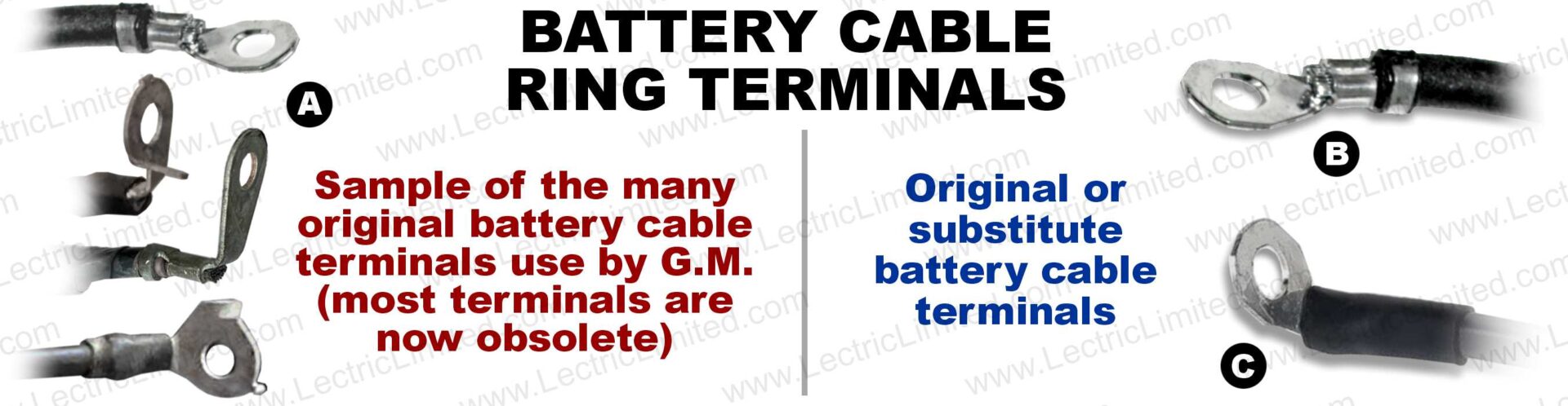
One of the terminals on my original battery cable does not match the terminal on your battery cable. Why not?
All of Lectric Limited’s battery cables come equipped with the factory-correct terminal on the end that connects directly to your battery. On the opposite end, General Motors used a variety of ring terminals, which could be straight, bent at different angles, and/or include an anti-rotation feature (see Figure A). We currently use one of these original-style terminals in our production (Figure B). However, many of the original terminals are now obsolete and no longer available. In such cases, rather than discontinuing those battery cables entirely, we use a functionally equivalent substitute terminal.
If a bent terminal is required for your application, we will make the appropriate bend during production (Figure C). If it’s not required but you still prefer a bend, you may carefully do it yourself using a bench vise and locking pliers for best results.
Why don’t some of the fuses in your fuse kit match the amperage printed on my fuse block or shown in the service manual?
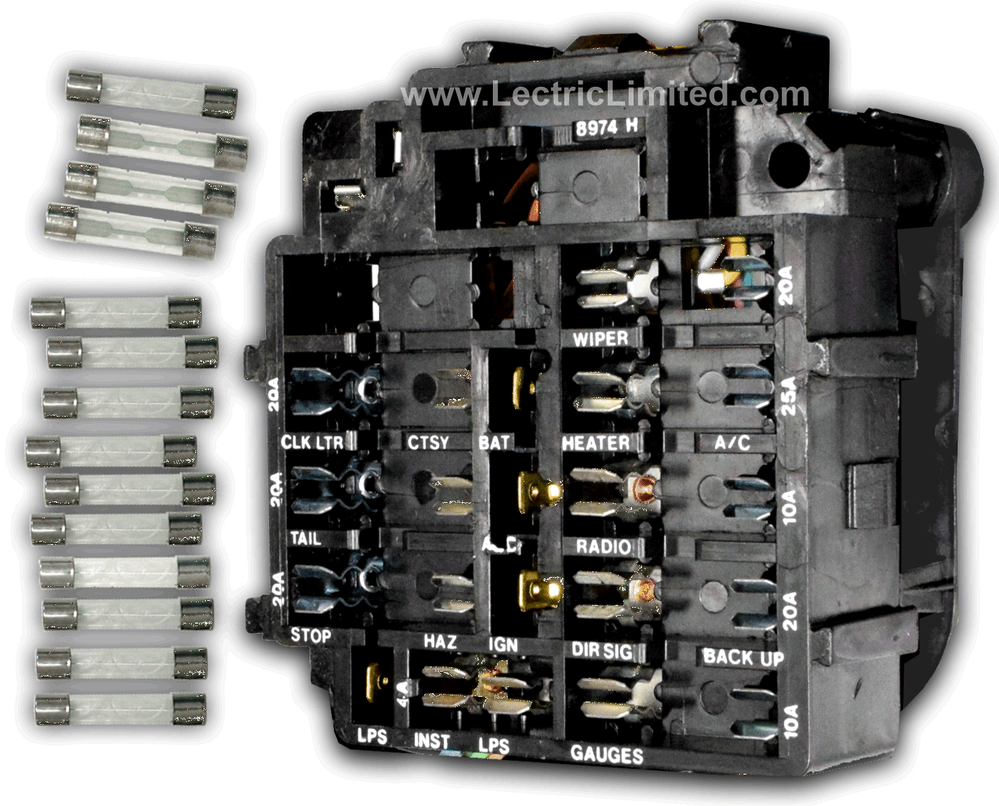
Both the amperage rating, as well as and the type of fuses we supply in our fuse kits ARE correct for your car. We know and understand that the amp rating that is printed (silk screened) on your fuse block may not necessarily match the amp rating of the fuses we supply in our kit. We also recognize that there may be discrepancies between what we supply in our kit and what is called for in the owner’s manual or service manual.
Believe it or not the fuse blocks were not always screened properly for a specific year/make/model vehicle, and as many of you are aware, owner’s manuals and service manuals are not always correct either.
We get our fuse information directly from the original assembly manuals. The assembly manual showed the assembly-line worker what fuses (based on part #) to install in the vehicle’s fuse block. Notice that the assembly manual does not even show the screen printing on the fuse block. It simply shows the part # and location for each fuse.
WARNING! Replacement (non-original) cigarette lighter housing should be modified or your wiring harness can burn!
According to the GM engineering drawings, the OEM cigarette lighter socket power wire for the following models was NOT FUSED:
- 1966 and earlier Chevrolet Fullsize, Corvette, Chevelle, Nova, and Corvair.
- 1972 and earlier Chevrolet and GMC truck.
- 1964 and earlier Pontiac Fullsize, GTO, Tempest, and Le Mans.
- 1964 and earlier Buick Skylark and Special.
- 1964 and earlier Oldsmobile Fullsize, Cutlass, F-85, and 442.
- 1957 Cadillac Fullsize.
This power wire was designed to only carry a load for a short period of time; just long enough to heat the lighter element. When the lighter “popped” out of the housing/socket, current flow would stop. This power wire provided a constant 12-volt battery power when the battery was connected.
Lectric Limited manufactures all “Original Design Series” OEM-style wiring harnesses to the original GM engineering drawing specifications. Consequently, the cigarette lighter power wire(s) on the cars listed above are NOT FUSED.
An unfused lighter socket should only be used for its intended function; as cigarette lighter. If used in any other application, the wire should be modified with an in-line fuse of an appropriate value. (Please be aware that even in the OEM application, it is still possible that the cigarette lighter can short-out and damage your harness, or worse). Any alteration or misuse of Lectric Limited products will void any manufacturer warranty.
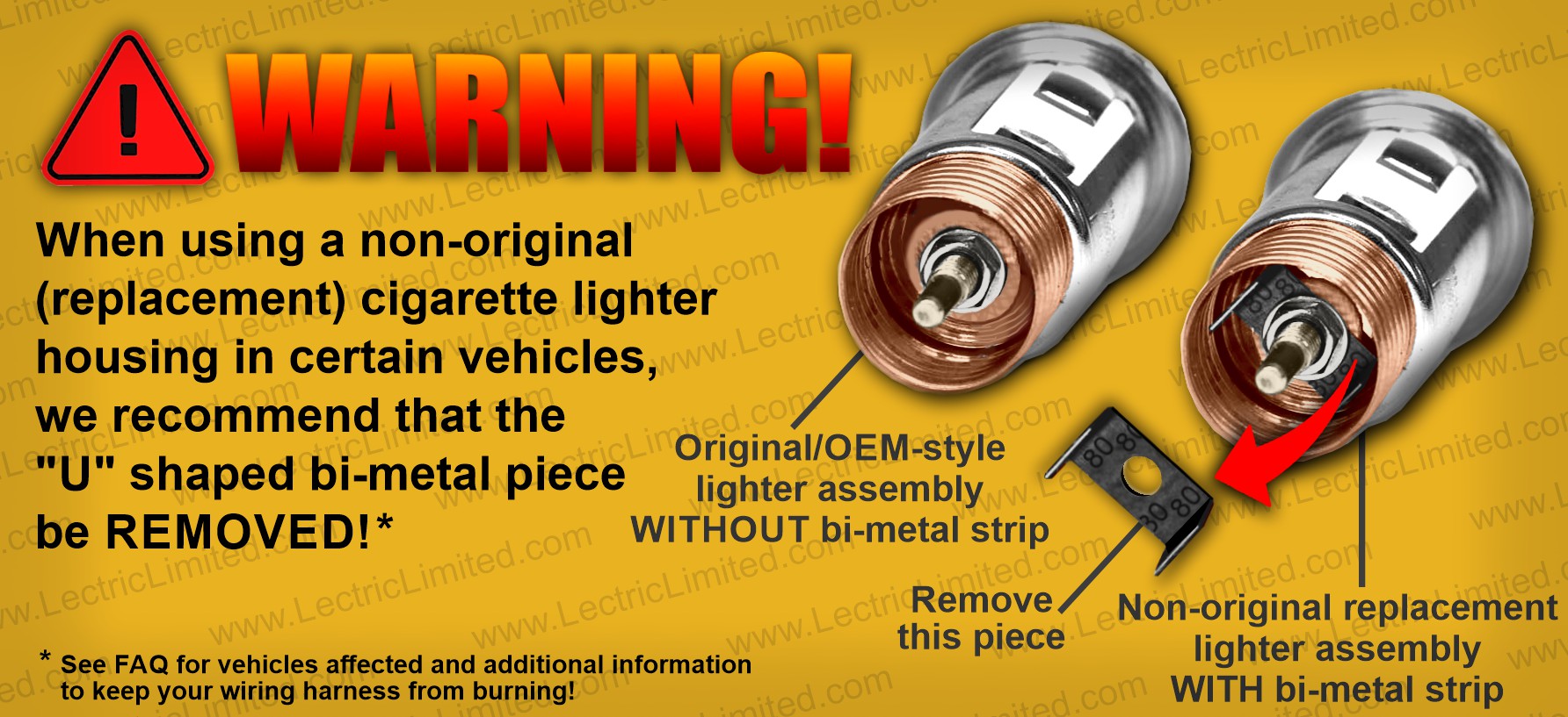
Many non-original replacement cigarette lighter socket assemblies include a bi-metal “U” shaped piece at the back of the socket assembly, which may be retained by a hex nut, where the power feed wire is connected. If overheated (due to an excessive load from applications such as a CB radio, power inverter, faulty phone charger, etc.), this bi-metal strip will expand BY DESIGN and purposely short-out the wire. In “newer” cars, this will simply blow the fuse that protected that wire, and not permit that wire from overheating and damaging the wiring harness(s), or worse.
WHY THE WARNING? If you are using a non-original replacement cigarette lighter socket assembly in a vehicle listed above or a vehicle with an un-fused power wire, and the bi-metal strip shorts-out the power wire, there is no fuse to protect that wire from burning. Consequently, Lectric Limited strongly recommends the removal of this bi-metal strip from the assembly, as shown in the graphic. Doing so will not protect the power wire from an overload but will eliminate the chance of a dead short caused by the bi-metal strip.
There was a recently discovered change by General Motors (and part manufacturer CASCO) in their current replacement cigarette lighter housings. This change could cause the housing to short circuit and thereby burn the wiring harness. The change is a small bi-metal element added to the rear of the housing where the power wire connects. It was added as an additional safety feature for cars with a fused cigarette lighter. The problem is that the cars listed above DO NOT have a fused cigarette lighter. Power to the lighter comes directly from the battery.
When installing this replacement cigarette lighter housing in one of the cars listed above, we highly recommend that you remove the bi-metal element! If you do not, and there is an overload situation, the bi-metal element will do its job and create a short-circuit to ground. However, this will also cause your wiring to burn!
The original GM part number for the lighter housing is #3986869. It was later replaced by #11516142. Virtually every part’s supplier sells this same housing. We recommend that all owners, of the vehicles listed above, should check their housing and remove the bi-metal element if present.
Help With Installation
How do I install my new wiring harness?

INSTALLATION INSTRUCTIONS: If your wiring harness included installation instructions, use them to help identify the destination and connection points for all terminals and connectors. The instructions may not show every wire or be drawn to scale. Using painter’s tape or masking tape, use this instruction sheet to label your new harness, at all its connection points, before you begin the installation process.
For an easier installation process, we suggest not removing your old harness entirely before installing the new one. Instead, remove the old harness step-by-step as you install the new one, allowing you to observe the original routing. Also, if the harness is not routed as original, it may not reach its intended devices.
If available for your vehicle, you can also consult a factory assembly manual for routing instructions. (Note: A ‘Service’ or ‘Shop’ Manual will usually not provide any information on harness routing). A Factory Assembly Manual contains general overview schematics, as well as line drawings of how to route the harnesses within your car. This manual is what the factory assembly line workers used to properly route the wires. They are available from your local restoration parts supplier and will simplify the installation of your new harness.
TAKE PHOTOS: Taking detailed reference photos of the old harness, particularly its routing and where it connects to, before removal is also recommended.
ASSEMBLER TAG: Every Lectric Limited wiring harness has a white assembler/manufacturing tag on it. This tag identifies the harness to us for tracking, troubleshooting, quality control, and warranty issues.
Before installation, verify that the part number on the tag matches the part number on the bag, and confirm that this is the correct harness for your needs. Please note that our dealers may repackage our products and/or use a different part number on their website/catalog/invoice. This tag also indicates that the harness has been thoroughly inspected before shipment. If there are any discrepancies, notify us or your dealer within 48 hours!
We highly recommend that you leave this assembler tag on. However, if you must remove it, please do so after the harness is fully installed, working properly, and you don’t foresee future technical questions about the harness.
Some of the wires in my new harness are not long enough. Why not?

On occasion we get phone calls from customers stating that a wire or two from our harness does not reach their intended device or ‘the wires are too short!’. This is usually due to the fact that the customer does not route the wires correctly. Routing a wire over something instead of under it, can make a big difference.
As a reference, we recommend that you purchase a Factory Assembly Manual (not a Shop or Service Manual). The Assembly Manual is what the factory assembly line workers used to properly route the wires – so they reach where they are supposed to. However, on rare occasions, we’ve found that the Assembly Manual is not always correct. (go figure). So please keep this in mind. If an assembly manual is not available for your vehicle, then you would need to look at an original car for wire routing information.
On other occasions, purchasing an aftermarket product can lead to the problem. For example, if you use an original Horn in your 1963-67 Corvette, your new wiring harness will reach the second horn and work perfectly. If you use an aftermarket or incorrect replacement horn, the terminals on that horn were not placed in the original location. And in this case, the wires leading to the horn will not reach if routed as original. In this instance, you would either need to purchase an original horn, make the wiring modification yourself, or determine a way to make the wires reach.
As we state throughout our website, we manufacture all of our wiring harnesses to the original blueprint specifications. This includes wire lengths. Also see FAQ question above.
How do I wire my GM starter motor?
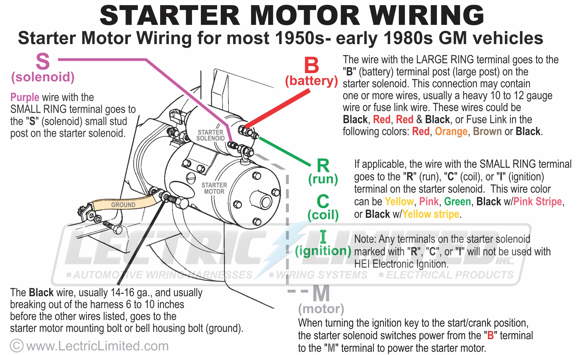
For most 1982 and earlier GM vehicles, the Purple wire with the ring terminal goes to the ‘S’ (solenoid) small stud post on the starter solenoid.
The other wire, if applicable, with the same size ring terminal as the Purple wire, goes to the ‘R’ (run) or ‘C’ (coil) terminal on the starter solenoid. This wire color can be Yellow, Pink, Green, Black w/Pink stripe, or Black w/Yellow stripe.
The wire with the large ring terminal goes to the ‘B’ (battery) terminal post (large post) on the starter solenoid. This connection may contain 1 or more wires, usually a heavy 10 or 12 gauge wire or fuse link wire. These wires could be Black, Red, Red & Black, or Fuse Link in the following colors: red, orange, brown or black.
The Black wire, usually 14-16 ga., and usually breaking out of the harness 6 to 10 inches before the wires listed above, goes to the starter motor mounting bolt or bell housing bolt (ground).
How do I remove my old (1966 to early 1980s) GM dash lamp sockets without damaging the socket or my dash cluster?
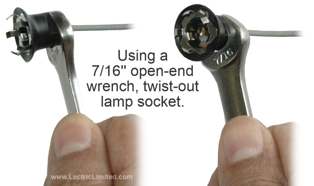
First of all, getting your hands behind your dash can be a bit of a struggle. But your task will be much easier if you follow this removal method.
These lamp sockets were designed with 2 flat sides. Get a 7/16” open-ended wrench and slide it into the flat sides of the socket. Use a twisting motion to pop-out the socket.
Do not pull the socket straight out! Doing so may separate the metal retainer from the plastic socket, and the socket will be ruined.
If these lamp sockets are damaged and need to be replaced, we do offer them under our “Repair Components”, part # VRC6577GL. New lamp sockets will be included with a new dash harness.
How do I install metal lamp sockets into my dash cluster?
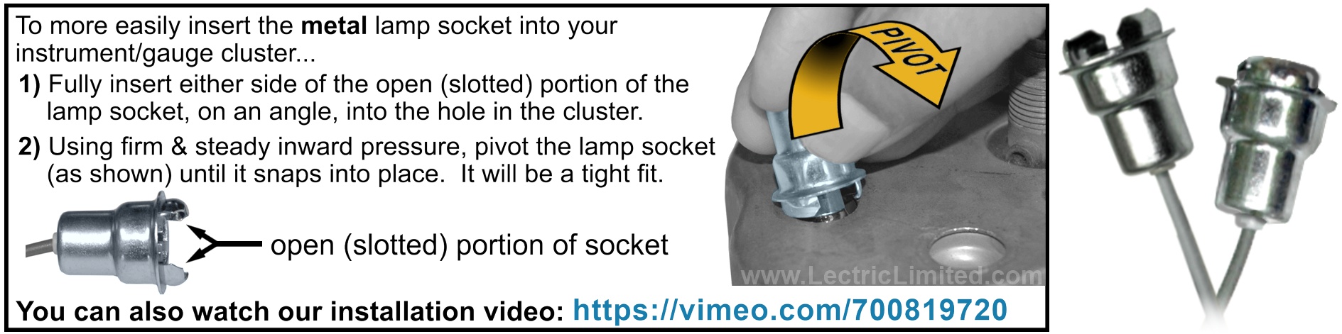
Periodically, we get calls from customers who find it difficult to insert, and snap-in our metal lamp sockets into the circular openings of their instrument cluster. The metal lamp sockets referred to are those shown to the right. These sockets are typically used on the dash harness we manufacture for 50-60 year-old cars.
Hopefully, this instructional video will give you a better insight into these lamp sockets and show you a technique to try to make them easier to install.
Why do my light bulbs inadvertently pop-out of my bulb sockets?
Periodically, we get these calls from our customers. This is especially evident with the numerous small bulbs in the dash harness. The problem is not the sockets. The problem (and solution) are your bulbs.
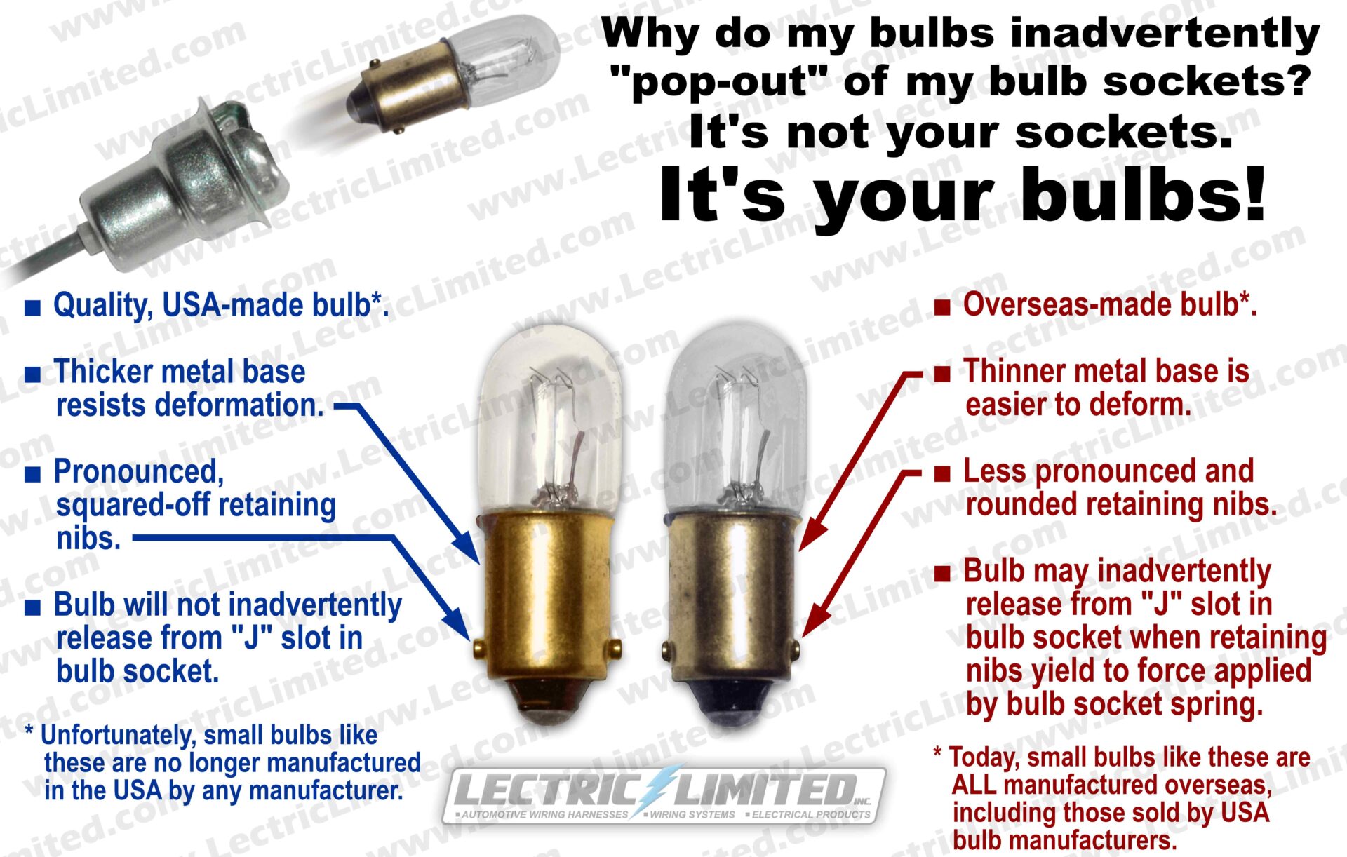
In addition, there is considerable variation in the manufacturing quality of overseas-made bulbs, depending on the manufacturer, reflecting inconsistencies in production standards and quality control processes.
How do wire my door jamb switches?
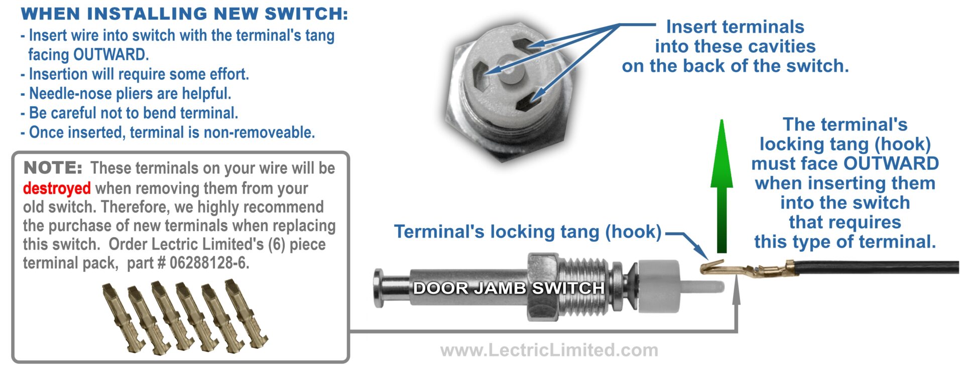
Door jamb switches control courtesy lights, dome lights, and door ajar indicators. When installing new or existing switches that require wires with locking hook-type terminals, ensure the terminals are inserted into the switch as depicted in the graphic above. This will guarantee the switches function correctly and reliably.
If you accidentally insert the terminals facing inward, you may attempt to pull them out to save the switch. However, this will destroy the terminals, so do not attempt to reuse them. If the terminal cavities of the switch are damaged, you will need to replace the entire switch as well.
Lectric Limited offers a 6-pack of replacement terminals, part #06288126-6.
How do I install my 1964-67 Corvette Transistor Ignition (T.I.) Auxiliary Harness?
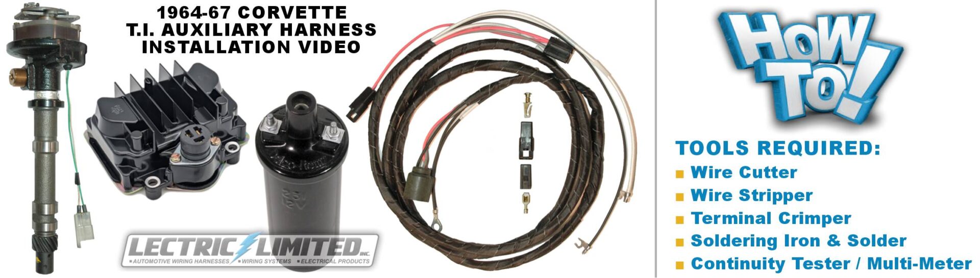
General Motors’ transistor ignition system (or T.I. system) was a factory-installed option that replaced mechanical ignition points with electronic ignition. From 1964-67, all Corvettes came down the assembly line with a Dash Harness and Engine Harnesses installed for a mechanical points ignition system. If T.I. ignition was ordered, both the existing Dash Harness and Engine Harness was modified, on the assembly line, to accommodate the T.I. components and an additional T.I. Auxiliary Harness.
In this video, you’ll see how to install a Transistor Ignition Auxiliary Harness, as installed in either a 1964-65 Corvette or 1966-67 Corvette.
Why does my bulkhead connector mounting bolt keep turning and never tighten?
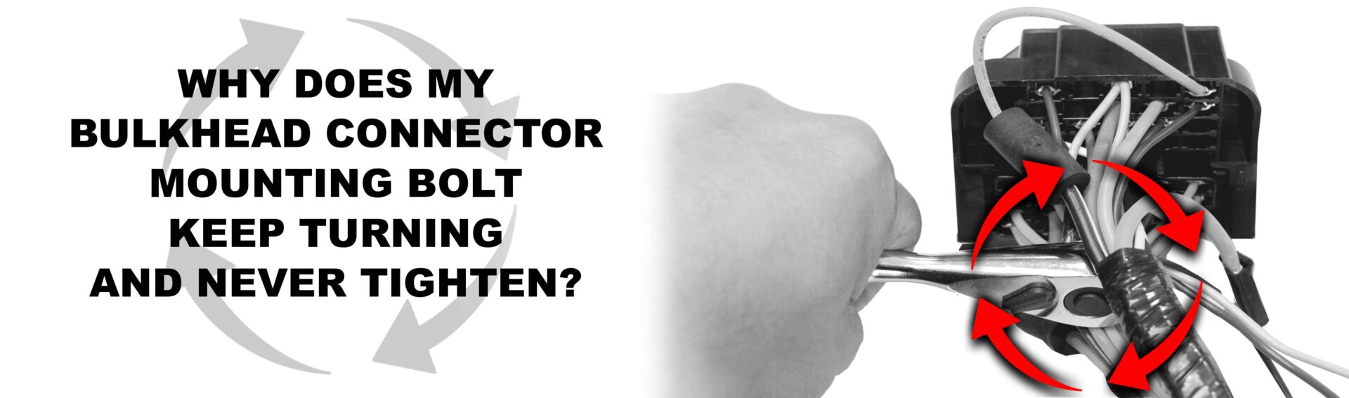
Starting in the late 1960s, some vehicles used a bolt to secure the bulkhead connector from the engine compartment side to the bulkhead connector that goes through the firewall. Although not common, the installer may experience a situation where, when attempting to tighten-down the mounting bolt, the bolt keeps turning and never tightens.
Please see our video as to the possible problem and solution.
How do I install my new Spark Plug Wires?
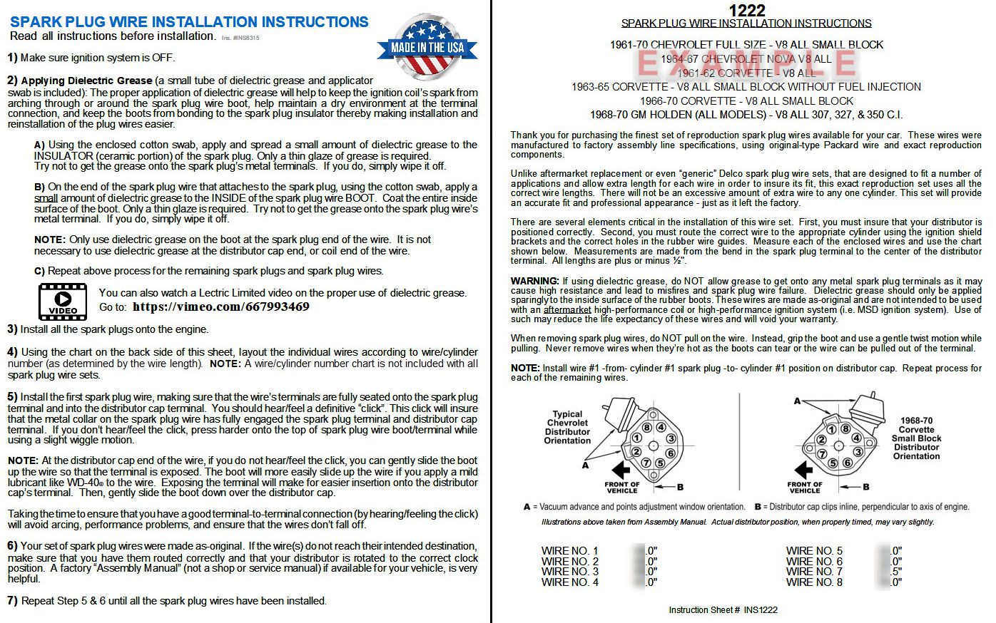
Here is the same, or similar, installation instruction that comes with our spark plug wire sets. Please read all instructions before installation.
1) Make sure ignition system is OFF.
IMPORTANT: There are several elements critical in the installation of spark plug wires. First, you must ensure that your distributor is positioned correctly. Second, if applicable, you must route the correct wire to the appropriate cylinder using the ignition shield brackets and the correct holes in the rubber wire guides.
2) MEASURE LENGTHS: Measure each of the wires and use the measurement chart we provide. Measurements are made from the bend in the spark plug terminal to the center of the distributor terminal. All lengths are plus or minus ½”.
3) DIELECTRIC GREASE: Applying dielectric grease (a small tube of dielectric grease and applicator swab will be included). Apply and spread a small amount of dielectric grease to the INSULATOR (ceramic portion) of the spark plug. Only a thin glaze of grease is required. Try not to get the grease onto the spark plug’s metal terminals. If you do, simply wipe it off.
When properly applied, dielectric grease will help to keep the ignition coil’s spark from arching through or around the spark plug wire boot, help maintain a dry environment at the terminal connection, and keep the boots from bonding to the spark plug insulator thereby making installation and reinstallation of the plug wires easier.
B) On the end of the spark plug wire that attaches to the spark plug, using the cotton swab, apply a small amount of dielectric grease to the INSIDE of the spark plug wire BOOT. Coat the entire inside surface of the boot. Only a thin glaze is required. Try not to get the grease onto the spark plug wire’s metal terminal. If you do, simply wipe it off.
NOTE: Only use dielectric grease on the boot at the spark plug end of the wire. It is not necessary to use dielectric grease at the distributor cap end, or coil end of the wire.
Repeat above process for the remaining spark plugs and spark plug wires.
You can also watch a Lectric Limited video on the proper use of dielectric grease: https://vimeo.com/667993469
4) Layout the individual wires according to wire/cylinder number (as determined by the wire length). NOTE: A wire/cylinder number chart is not included with all spark plug wire sets.
5) INSTALL: Install the first spark plug wire, making sure that the wire’s terminals are fully seated onto the spark plug terminal and into the distributor cap terminal. You should hear/feel a definitive “click”. This click will ensure that the metal collar on the spark plug wire has fully engaged the spark plug terminal and distributor cap terminal. If you don’t hear/feel the click, press harder onto the top of spark plug wire boot/terminal while using a slight wiggle motion.
NOTE: Unlike aftermarket replacement or even “generic” Delco spark plug wire sets, that are designed to fit a number of applications and allow extra length for each wire in order to insure its fit, this exact reproduction set uses all the correct wire lengths. There will not be an excessive amount of extra wire to any one cylinder. This set will provide an accurate fit and professional appearance – just as it left the factory.
NOTE: At the distributor cap end of the wire, if you do not hear/feel the click, you can gently slide the boot up the wire so that the terminal is exposed. The boot will more easily slide up the wire if you apply a mild lubricant like WD-40® to the wire. Exposing the terminal will make for easier insertion onto the distributor cap’s terminal. Then, gently slide the boot down over the distributor cap.
Taking the time to ensure that you have a good terminal-to-terminal connection (by hearing/feeling the click) will avoid arcing, performance problems, and ensure that the wires don’t fall off.
6) Your set of spark plug wires were made as-original. If the wire(s) do not reach their intended destination, make sure that you have them routed correctly and that your distributor is rotated to the correct clock position. A factory “Assembly Manual” (not a shop or service manual) if available for your vehicle, is very helpful.
7) Repeat until all spark plug wires have been installed.
REMOVAL: When removing spark plug wires, do NOT pull on the wire. Instead, grip the boot and use a gentle twist motion while pulling. Never remove wires when they’re hot as the boots can tear or the wire can be pulled out of the terminal. This will void your warranty.
Is my brown battery cable the negative or positive?
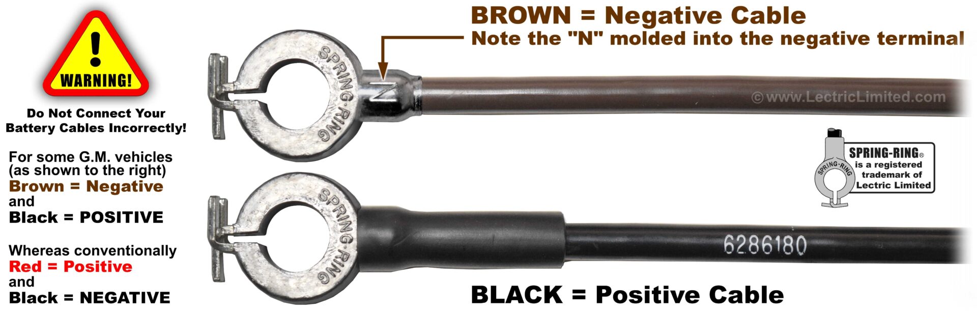
The standard/conventional color for the negative battery cable has been black. However, although it was not common, BROWN is the NEGATIVE on battery cables having Spring-Ring terminals. These brown (negative) battery cables were used in some General Motors vehicles during the 1960s, particularly in specific models like the Chevrolet Corvette, Chevrolet Full-Size, and some Chevrolet trucks. This was part of a color-coding system for some vehicles, primarily in the performance lines. However, this was not a widespread practice across all GM vehicles.
WARNING! We get more than a few phone calls from customers who accidently connected the brown battery cable to the positive battery terminal and now need to purchase all new wiring and other electrical components. Do not make this mistake! Before connecting your cables to your battery, look for the polarity on the terminals, either N , P, – , or +.
Should I install my battery disconnect switch on the positive or negative battery terminal?
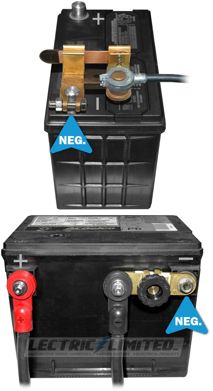
A battery disconnect switch makes it convenient to isolate the battery from any potential draws when the ignition switch is off (like a clock, radio display, glove box light, computer, etc.) and it’s much more convenient to turn a knob or move a lever than to keep removing the battery cables from the battery.
You also want to remove the battery as a power source when doing any work on the car that involves the electrical system, especially on earlier cars that have many un-fused, ignition-off, battery-fed circuits and don’t have fusible links on the primary power feed circuits; harnesses are expensive, and dead shorts can cause a fire.
Battery disconnects are designed to be installed on the NEGATIVE (Ground) battery terminal. The negative battery terminal is smaller in diameter than the positive terminal. Correspondingly, the battery disconnects have the smaller hole where they attach to the battery (and the smaller terminal size where the negative cable attaches to the disconnect switch).
Electrically speaking, it doesn’t matter if you disconnect the positive or negative side of the battery. But safety is another matter.
Disconnecting the positive side will kill power to the harnesses, but there’s still a ground path back to the battery. If you drop a wrench and it touches the battery positive terminal and the engine, it will create a 500 to 700-amp dead short – which could damage (or destroy) your battery (and even melt your wrench).
If you disconnect the negative side (as all disconnects are designed to do) and drop a wrench that touches the battery positive terminal and the engine, nothing will happen, as there is no ground path from anything in the car back to the battery to complete the circuit.
It’s Not Working (General Problems)
Why is my temperature gauge intermittent or not working at all?
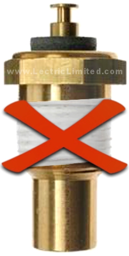
Assuming your temperature gauge, temperature sending unit, and wiring are all functioning properly, one common cause of inoperable or intermittent gauges is the use of Teflon or pipe tape sealant on the sending unit’s threads.
Avoid using Teflon (pipe) tape, thread sealant, or any other material on the threads of the sending unit. The tapered threads are designed to create a tighter seal as they are screwed in. If you feel it’s necessary to prevent leaks, you can use pipe thread sealant or tape but do so sparingly.
Any material between the sending unit threads and the car’s ground (the engine) can disrupt the gauge’s functionality. Without a proper ground connection, your temperature gauge will likely show a constant reading around 100 degrees (pegged to the left, on the cold side), regardless of the engine’s actual temperature. If the sending unit has a poor ground due to Teflon tape or sealant, the gauge may display a cooler reading than the engine’s true temperature.
Additionally, never over-tighten the nuts on the back of the temperature gauge. A delicate wire is connected to those nuts, and overtightening can break this wire, causing the gauge to malfunction. This could lead to the gauge either not working or fluctuating while driving as the wire makes and breaks contact.
Did you know Lectric Limited offers precise replacement Temperature Sending Units? These units will ensure your temperature gauge reads accurately—provided you’ve addressed the potential issues mentioned above.
Why isn’t my temperature gauge accurate?
Part 1
The 1st possible problem:
Your temperature sending unit is defective or is the wrong type (wrong resistance/thermistor).
Most likely you, or a previous owner, had installed a generic sending unit. Auto supply stores carry generic sending units that will fit and function in your engine,. But because these sending units cover a broad range of years/makes/models, they do not have the same precision resistance rating as the factory sending unit specifically designed for your year/make/model car.
These generic replacement sending units may either work or may give inaccurate readings. It would now be up to you to determine if your gauge displays an accurate reading.
We can solve your first problem. Lectric Limited offers accurate replacement Temperature Sending Units that will perform as-original. These sending units will make your temperature gauge read accurately (provided you have resolved the following problems).
The 2nd possible problem:
If your temperature gauge originally had a resistor bridging the silver post (ground) and the copper post directly across, this resistor may be missing. This is typically a 90 ohm ceramic resistor and must be used.
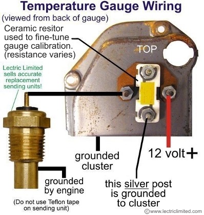
To the right is a diagram of how a typical temperature gauge should be wired.
If the value of the resistor, on the back of the gauge, bridging the silver post and the copper post directly across, is too high, your gauge will read hotter than the engine’s actual temperature. With no resistor (high resistance state) your gauge will peg to the right. (Note: The correlation between resistance and the gauge display is exactly the opposite when adding more resistance in series with the sending unit. If you add more resistance in series with the sending unit, your gauge will display cooler than the engine’s actual temperature.)
If the value of that resistor on the back of the gauge is too low, your gauge will read cooler than the engine’s actual temperature. With shorted terminals (no resistance state) your gauge will peg to the left. (Note: The correlation between resistance of the sending unit and the gauge display is exactly the opposite. If you could subtract the resistance of the sending unit, your gauge will display hotter than the engine’s actual temperature.)
The 3rd possible problem:
You do not have your gauge wired properly. Below is how a typical temperature gauge, with 4 terminals, should be wired. Also shown are 2 ways that you can ‘fool’ your gauge to display/read cooler. Although we recommend using the correct temperature sending unit, adding an external resistor is an option.
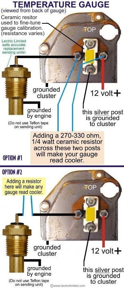
Notice! Jury rigging your car’s temperature reporting system to force it to read ‘accurately’ under normal conditions without first understanding which component(s) of the system are off can be very dangerous. For example, if you ‘fix’ a temperature gauge with a 50 ohm resistor, when in fact the gauge was operating correctly, could result in your gauge displaying an acceptable 190 degrees (normal driving temp.) when your car is actually operating at a dangerous 260 degrees. Use your discretion.
The 4th possible problem:
Sometimes, in order to correct an inaccurate gauge reading, previous car owners have been known to install a resistor in series with their temperature gauge. Unknown to you, you may have a hidden resistor somewhere between your temperature sending unit and gauge. Additional resistance will cause your gauge to display/read cooler than the actual engine temperature. This resistor needs to be removed in order to give you an accurate gauge reading with our new, accurate sending units.
The 5th possible problem:
Did you use Teflon tape or pipe thread sealant on the threads of your sending unit? If you did, try removing it and see if that corrects the problem. Note: If you must use something to keep your sending unit from leaking, you can use pipe thread sealant but do so sparingly.
Any material between the threads of the sending unit and the car’s ground (engine) can result in your gauge working improperly, or not working at all. Without the sending unit being grounded, your temperature gauge will show an approximate 100 degree reading (pegged to the left, cold side, of the gauge) no matter what the engine’s temperature. If your sending gauge is making a poor (high-resistance) ground to the engine because of Teflon tape or pipe thread sealant, your gauge will display/read cooler than the actual engine temperature.
Part 2
IT’S A FACT that the original 1963-65 Corvette (and possibly other GM vehicle’s) temperature gauge was not accurate!!!
The gauge displayed a reading that was higher than the actual engine temperature. Consequently, your car may be within standard operating temperature even though your gauge reads hot.
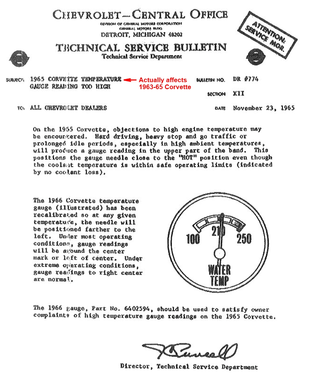
A Technical Service Bulletin (TSB) addressing this flaw (shown right) was issued by Chevrolet in November 1965 (which actually affected 1963-65 Corvette).
The internals of the 1963, ’64 & ’65 temperature gauge were electrically the same.
The ’63 was cosmetically similar to the ’64, but much different than the ’66 gauge. Therefore, replacing a ’63 or ’64 gauge with a ’66 gauge was unacceptable for many owners. However, since the ’65 gauge was cosmetically similar to the ’66 gauge, the ’66 gauge (that functioned properly) was a suitable replacement for the ’65 gauge.
We can only assume that this is the reason the TSB does not specifically address the 1963-64 Corvette gauges, even though the gauge flaw applied to those years.
Please note that our replacement temperature sending unit will not correct this factory flaw. To correct the flaw in 1963-66 Corvette gauges, you may need to install a 270 – 330 ohm, 1/4 watt ceramic resistor across the 2 posts. This should supply your gauge with the correct resistance in order to read more accurately.
A resistor may be added to make your 1963-82 (approx.) gauge read cooler, and closer to the actual engine temperature (thus compensating for the gauge flaw). There are 2 options shown:
- OPTION #1: Using 330 ohms as a base line (meaning to start with a 330 ohm resistor), the more you decrease the resistance, say from 330 to 270 ohms, the cooler the gauge will display. In effect a 270 ohm resistor will make your gauge read slightly cooler than by using a 330 ohm resistor – with the resistor placed between the 2 posts as shown in the diagram above. We do not have specifications correlating ohms to temperature. You will just have to try different value resistors until your gauge displays the actual engine temperature. CAUTION: Do not install too low a value resistor, or you may short-circuit the posts. NOTE: Do not confuse the resistor of this value and in this location (between the 2 posts on the gauge itself) with the resistor mentioned in Option #2 (below).
- OPTION #2: On any gauge, you can add a resistor at some point between your temperature sending unit and your gauge. The higher the resistor value, the cooler your gauge will display. We do not have specifications correlating ohms to temperature. You will just have to try different value resistors until your gauge displays the actual engine temperature. A suggestion is to start with a 5 or 10 ohm resistor. Keep adding resistance until you get the desired gauge reading.
I’m having problems with my T.I. (Transistorized Ignition) system. What could the problem be?

Almost all of the time, your problem can be resolved by addressing one or more of the issues shown below:
(Part 1)
- Did you know that many times a problem with an original T.I. system can be traced back to the electronic components. Many years ago, when the T.I. system was developed, Germanium transistors were ‘state-of-the-art’ in electronic technology. This type of transistor, however, had many limitations and many amplifier failures can be traced back to these transistors. Our VTR6571AM replacement module uses the newer-type Silicone transistors that rarely fail. Other problems that led to amplifier failure were due to water from a faulty cover seal. Moisture trapped inside the amplifier box will cause corrosion to the extent it will rust electrical component leads and destroy copper tracks (traces) on the printed circuit board, thus leading to failure. All of the electronic components in our VTR6571AM are completely encapsulated/sealed. If water does get trapped inside your box, the VTR6571AM will not be affected.
- If you install one of our VTR6571AM modules and are having problems with your T.I. system not functioning, 99% of the time the problem lies in the female terminals in the Amplifier Box Extension wiring. This wiring connects the module to your wiring harness. The electrical connections must be perfect – there is a very small tolerance within the T.I. system for any unnecessary resistance. The electrical connections are the weakest link in this system.
- Over the years, the spring-tension on these female terminals will lose their ‘grip’ on the male terminals they connect to. The T.I. system draws up to 7 amps so it needs all the current it can get. And a voltage drop of only a 1/2 volt will cause your module to fail. It is IMPERATIVE that the Amplifier Box Extension wiring be replaced when installing a new T.I. Box Module. Don’t fool yourself into thinking ‘My old wiring looks good. It’ll be fine’. It won’t be!
We offer two different T.I. Amplifier Box Extensions. The Lectric Limited part #VTR6468BXT is for 1964 to early 1968 Corvettes, 1966 Chevy II/Nova, 1964-66 Tempest/Le Mans GTO, 1964-66 Pontiac Full-Size. Part #VTR6871BXT is for 1968 (2nd design) thru 1971 Corvettes and 1969 Camaros.
(Part 2)
Another cause of a non-functioning replacement T.I. Box Module (our VTR6571AM) can be corrected by simply charging your battery. An original T.I. amplifier board requires .4 to .7 volts AC to begin ‘switching’. Our replacement T.I. amplifier box module (VTR6571AM), with more robust circuitry, requires at least 1 volt AC to switch. This may not sound like much of a difference, but it equates to about 40% more voltage. Therefore, when cranking your engine, if your battery doesn’t spin your starter (and distributor) fast enough, and/or the pickup coil is not generating the minimal required AC voltage, the ignition system will not function. So, keep your battery fully charged.
(Part 3)
Are you using the right ignition coil? Another cause of a non-functioning T.I. system may lie within the ignition coil. The T.I. coil is unique to this system as it is powered by a higher primary voltage and has a greater number of secondary windings than a ‘points system’ coil – creating greater spark energy. Keep in mind that a points ignition system switches the coil’s negative terminal. A T.I. system switches the coil’s positive terminal.
(Part 4)
And finally, check your grounds!!! Corvettes (being made of fiberglass) are very prone to grounding issues.
Why does my ammeter gauge always display ‘discharge’?
If your ammeter does not display correctly, a possible problem may be:
- ammeter wired backwards
- faulty switch or relay
- defective alternator/generator or voltage regulator
- stuck relays
- incorrectly manufactured ammeter (see below)
NOTICE! 1970-72 Chevelle, El Camino & Monte Carlo: It has come to our attention that there are some ‘reproduction’ gauges being sold in the restoration marketplace that have been manufactured incorrectly. If your new Lectric Limited dash harness or tachometer harness is installed using these incorrectly manufactured replacement gauges, your AMMETER MAY READ BACKWARDS. This is not an issue with your new wiring harness, it’s a problem with the replacement ammeter gauge.
All Lectric Limited harnesses have been manufactured to the exact specifications of the GM engineering drawing for the year and application of your vehicle. It will install and operate properly with all OEM factory AC Delco gauges.
Prior to installing your new harness, please determine if the gauges in your car, especially the ammeter, are OEM GM gauges or aftermarket replacements. If they are aftermarket replacements, contact the seller or manufacturer that you purchased them from (not Lectric Limited) to see what you must do for your gauges to operate and read properly.
Why do my 1953-62 Corvette gauges fluctuate when I hit the brake pedal or use my turn signals?
There is NOT a problem with your Lectric Limited wiring harness. This is ‘normal’ (so to speak). The original wiring for a 53-62 Corvette was, in fact, not designed properly by GM. The problem is a result of inadequate grounding, compounded with RFI signals being sent through the power circuits to the gauges.
Numerous studies have determined that there’s nothing you can do about this problem with the existing, original wiring. Even by adding additional grounds, this problem will not be corrected. It’s a GM design flaw you’ll have to live with.
Why don’t my turn signals and/or hazard lights flash, or flash improperly?
You probably have one or more of the following problems:
- Non-working bulb(s)
- Incorrect bulb(s). Using 1-contact bulb in a 2-contact lamp socket. They may physically fit but will either not work properly or short-circuit and blow a fuse. See other FAQ question.
- Using LED bulb(s)
- Defective turn signal flasher
- Wrong turn signal flasher
- Defective turn signal switch
- Bad wiring
- Bad ground(s)
For some cars, we offer complete fuse & flasher kits with all the properly rated fuses and lamp flashers. See our online catalog for your application.
There are ‘gremlins’ in my electrical system. Weird things are happening. What do I do?
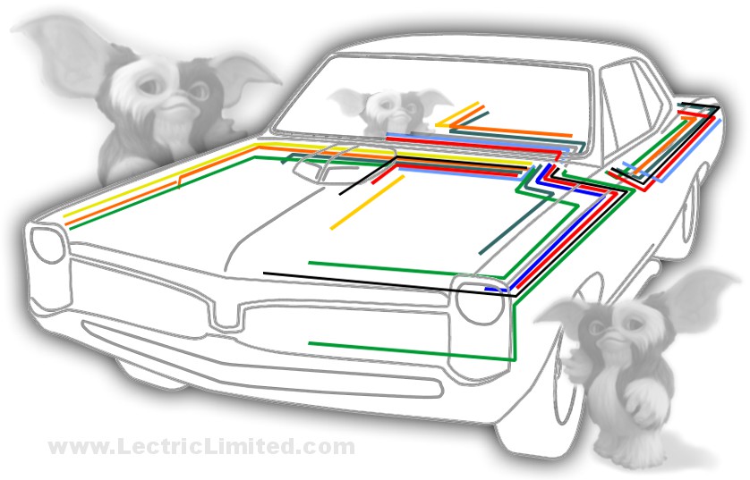
Sometimes, electrical issues can be baffling. Intermittent instrument readings, unexpected flashing lights not linked to turn signals, a dome light activating when the brakes are applied, or the radio turning on with the turn signals—all these odd behaviors often point to a ‘floating ground,’ where electrons are searching for any available path back to the battery.
In many cases, critical ground wires are overlooked during restoration, or the grounding points on the chassis, engine, and other components are either corroded or not properly secured. Corrosion might not be visible until the terminal is removed and inspected.
Ensure that the chassis, engine, and all other necessary grounding points have a solid, reliable connection to the negative side of the battery. The timeless advice remains: ‘Check your grounds!’
My Corvette has electrical components that don’t work. What’s the cause?
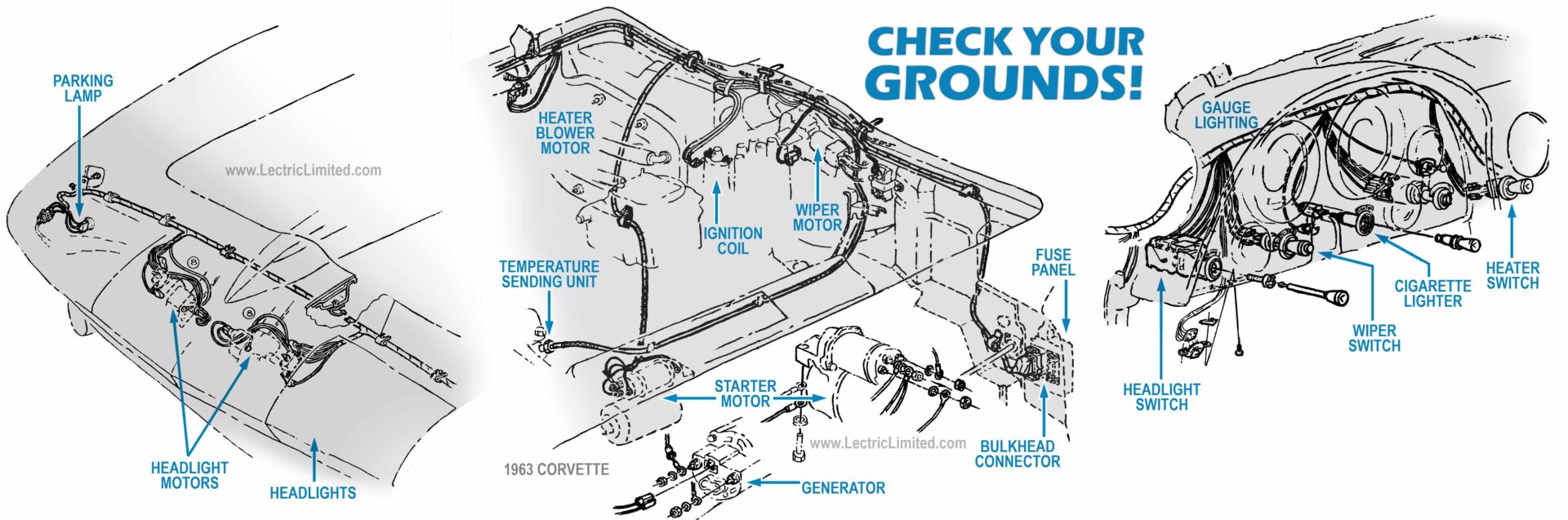
A Corvette’s body is constructed from fiberglass, which does not conduct electricity. Consequently, it’s crucial that the entire grounding system is flawless, with all component and chassis grounds properly connected and free from corrosion. As the saying goes, ‘Check your grounds’—this is especially important for a Corvette.
Refer to the factory ‘Assembly Manual’ (not a shop or service manual) for guidance on the location of these ground wires. We also offer ground lead wires, ground cables and ground straps to help ensure a solid grounding system.
My harness burned. Where do I start looking for the cause?
Let’s make the assumption that you just installed a new Lectric Limited harness. Our harnesses are circuit tested to ensure that the harness is factory perfect before you install it. That being said, the most common causes for a burnt harness are a:
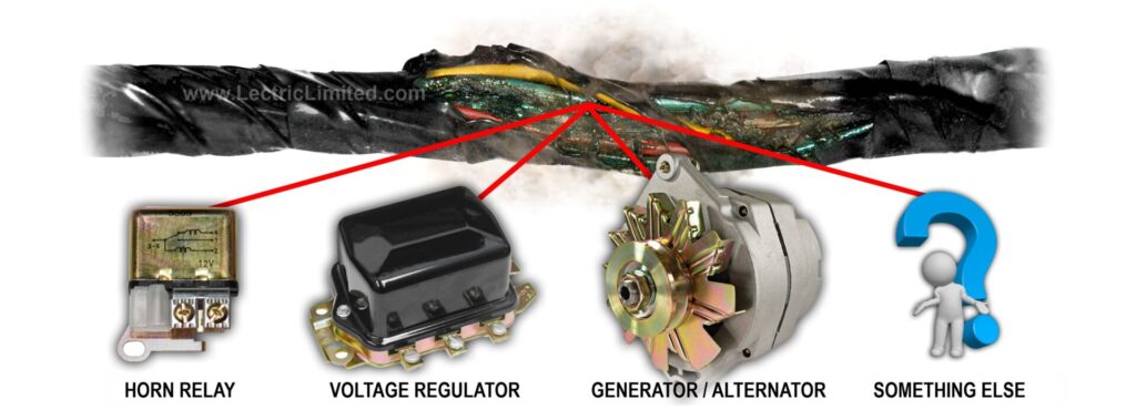
1.) Faulty Horn Relay
2.) Faulty Voltage Regulator
3.) Faulty Generator/Alternator
From our experience, when a customer’s harness has burned out, checking the continuity of the terminal posts on the horn relay, voltage regulator, and/or generator/alternator often reveals that at least one component is shorted to ground. A harness that’s shorted to ground can burn in seconds.
Be cautious with ‘rebuilt’ horn relays, as they could merely be re-plated and re-painted without being electrically tested or having new windings and contacts. The same applies to voltage regulators and alternators. Don’t assume that a ‘rebuilt’ part will perform like new.
I think I have an electrical short because my battery keeps draining. How do I locate the cause?
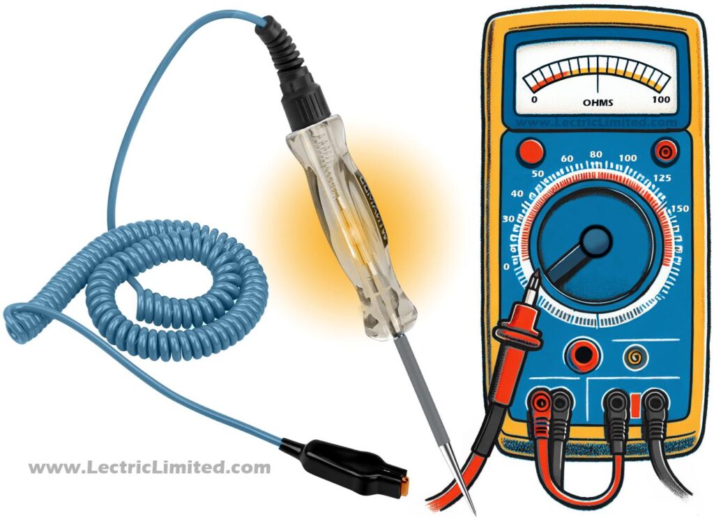
Finding an electrical short can be one of the most frustrating and time-consuming problems in owning an antique vehicle (or any vehicle for that matter). But where do you start to isolate the cause of the problem?
Here’s the scenario: Every couple of days you have to jump start your car because the battery has drained down to the point where the car won’t start.
As with all scenarios, we have to make some assumptions. We have to assume that your battery is good and was fully charged, that your charging system is good, that you are not blowing fuses or fusible links, that you did not leave any lights on (interior, glove box, under-hood, etc.) and that you did not leave your car’s ignition in the ‘run’ position with the engine off. If all these were checked, you probably have something that is drawing enough power to drain the battery (short?), but not sufficient enough to blow a fuse or fusible link in a protected circuit.
Let’s try to locate the possible short. If you have a test light (easily obtained at any auto part’s store) disconnect the negative battery cable from the battery. Connect the lead from your test light to the negative battery cable and connect the other end of your test light to the negative battery post. An assistant or 2 small hose clamps will help hold your test light in place. (An ammeter (not a voltmeter) will be a more accurate substitute for a test light assuming you can read an ammeter. Normal constant draw on the battery is about 200ma.)
On your test light, you may get:
- No light. This means no power draw (no problem) or a bad connection on your test light (fix & re-try).
- A quick flash of the light, then nothing. This may be normal as the capacitors in the electronics charge up.
- Constant light. This is probably what most people will see. Whether you have a problem or not. Small devices like clocks, radio displays, etc. will constantly draw a SMALL amount of power and cause the test light to dimly glow. This is normal. If your test light glows very bright, you have a problem with something drawing too much current.
It’s Not Working (Lectric Limited Products)
I bought a new windshield wiper motor, but it’s not working properly. What do I do now?
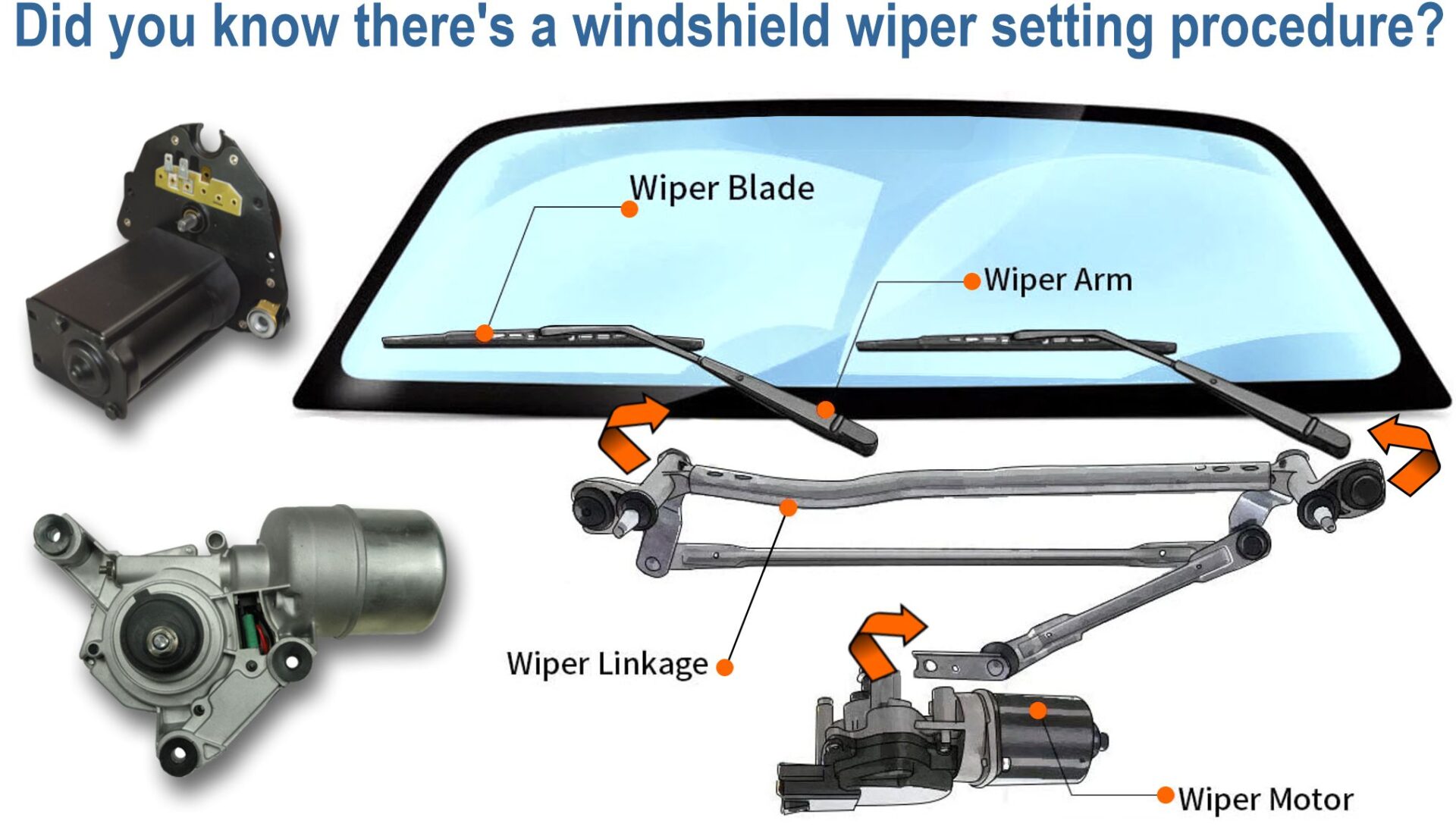
WARNING: Lectric Limited’s windshield wiper motors are factory-set in the park position. DO NOT BENCH TEST or rotate drive shaft prior to complete installation. Doing so can cause damage to your motor, possibly your vehicle, and will VOID YOUR WARRANTY! Lectric Limited cannot re-park your motor.
Installing and adjusting a windshield wiper motor can be a detailed process depending on the year, make and model of your vehicle.
Once the motor is installed, it’s important to adjust the linkage and wipers correctly, according to the vehicle manufacturer’s instructions. The use of a factory assembly manual can be very helpful. For your convenience, we are providing windshield wiper setting procedures for some vehicles. These procedures are derived from the factory assembly manual. See links below. More vehicles coming soon!
I bought a new temperature sending unit from Lectric Limited. But the terminal from my old harness does not fit it. Why not?
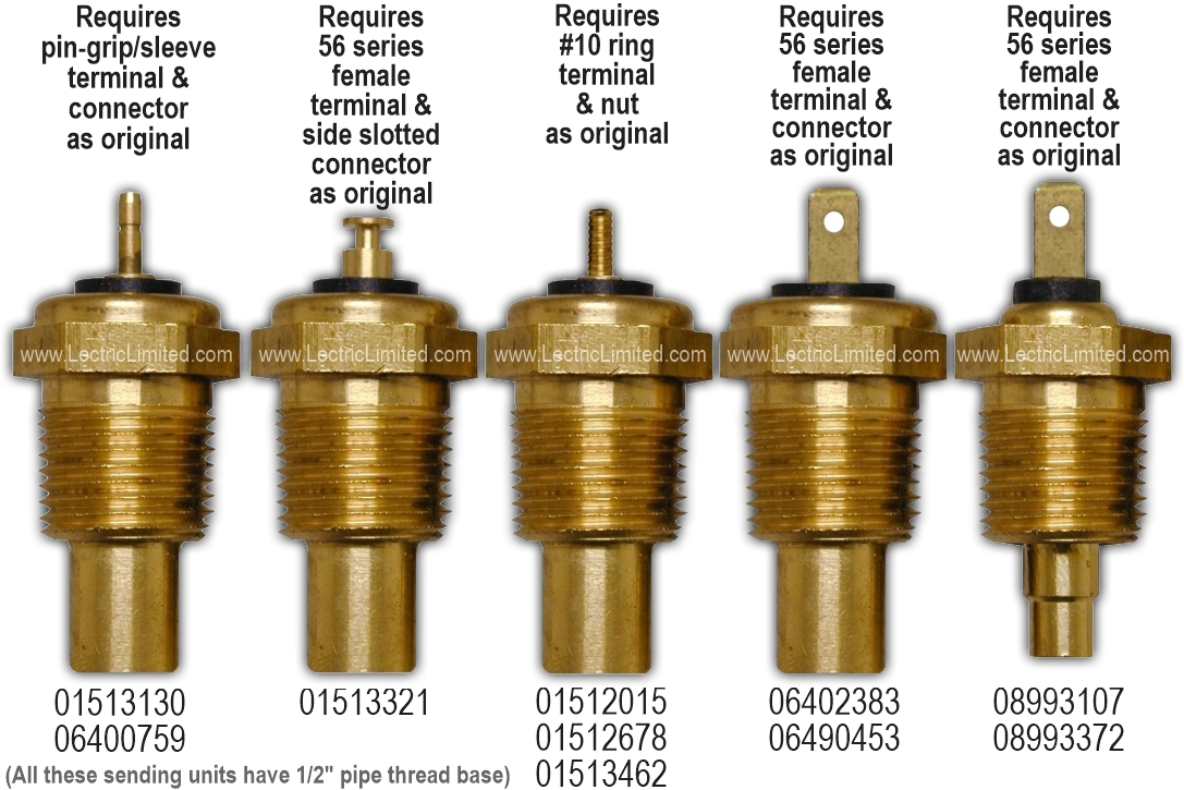
All of our temperature sending units are manufactured to the original GM blueprint specifications. They have the same internal thermistor (sensing device), 1/2” diameter tapered pipe thread base (not the smaller 3/8”), and top terminal connection type, as they had originally.
However, through the years, the mating terminal and connector on your harness may have been changed by you, a previous owner, or a repair shop. This change was most likely made in order to try different sending units when the ‘exact replacement’ unit didn’t work or was not available.
If your harness had been modified from original, we do offer replacement Temperature Sending Unit Lead Repair Kits.
In addition, part# 01513321 (with the ‘T’ shaped terminal) was typically used on cars with the sending unit positioned in the INTAKE MANIFOLD.
All the other sending units shown, were typically used on cars with the sending unit mounted in the CYLINDER HEAD. This straight-in type connection either prevents the sending unit wire from rotating, or, if the wire can rotate (as with sending unit #01513130), will not rotate in such a way as to come in contact with the hot exhaust manifold and melt.
The point we’re trying to make is that when a customer calls and says, ‘You sent me the wrong sending unit. The sending unit I’m supposed to have looks like the T-type, but you sent me the threaded-post type.” The first question we ask is, ‘Where does your sending unit screw into?’. If they say the cylinder head, then we know the customer is mistaken. We know this because GM would never use a sending unit that could allow the sending unit wire to melt on the hot exhaust manifold.
I don’t think my temperature sending unit is accurate. What could be wrong?
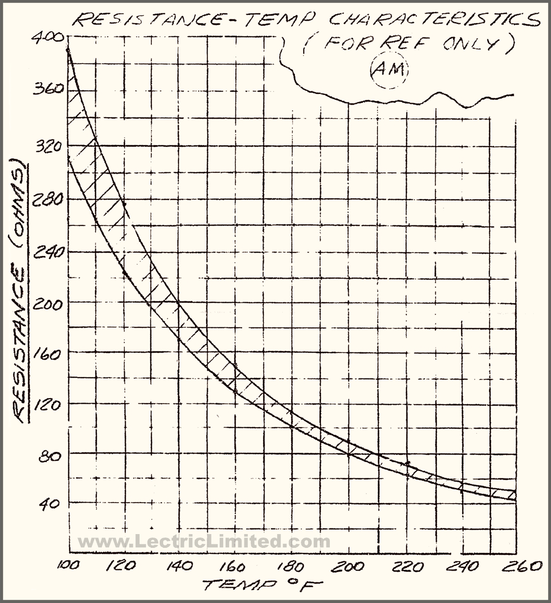
Let’s face it, even though we restore and maintain our classic cars, we are dealing with 50-60 year old technology and, many times, original components (gauge, wiring, voltage regulator, alternator/generator, etc.). Yet the temperature accuracy of a new car’s temperature gauge is only slightly more accurate than in the past.
If you look at your classic car’s temperature gauge, you’ll note there are very few temperature reference points. You’ll see something like a 100-120 deg. F indication at the low end, a mid-scale 180-210 deg. F area, and a somewhat detailed high end warning area in the 230-260 deg. F range. Why? Because GM (and most other manufacturers) was not trying to design a precision thermometer found in a laboratory. GM was looking for an inexpensive, high-production-run system that would give the driver a reasonably accurate visual indication of the mid-range engine temperature, and accurately predict a bona fide engine overheating threat. (You can forget about accuracy below 140 degrees.) So as long as your vehicle was not over-heating, GM was not concerned if your gauge displayed 198 degrees, as opposed to the true temperature of 220 degrees, for example.
Without getting into too much technical mumbo-jumbo, all automotive sending units are calibrated on a ‘temperature vs. resistance’ ratio scale that is exponential (a curve) and not linear (a straight line).
The response curve of the temperature sending unit is ‘bounded’ by upper and lower exponential curves. These curves form an ‘acceptable’ range where individually manufactured parts can vary in precision. This is what is called the ‘+ or -‘ accuracy range. The acceptable range is wide at low temperatures (around 120 deg. F) and is refined, or more accurate, at the high end of the gauge (around 230-260 deg. F).
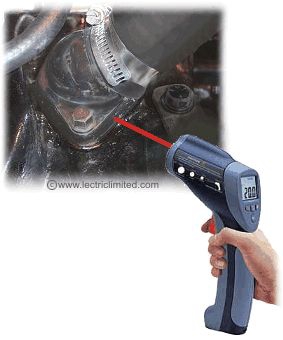
NOTE: This exponential curve of temperature vs. resistance is why you cannot determine if your sending unit is good or bad by taking a resistance (ohm) reading below, say 180 degrees. If you do, your assumptions as to the accuracy of the sending unit at operating temperature will not be correct.
So, if your true engine temperature is 220 degrees F. Assuming all other conditions that effect a gauge reading are operating perfectly, an original GM sending unit will display a gauge reading between 198 deg. and 242 degrees. This is a + or – 10% accuracy. This is considered an acceptable display range. All Lectric Limited’s sending units meet or perform better than this GM specified range. In addition, we quality control test all our sending units at the time of manufacture.
In accordance with the original GM blueprint specifications, all Lectric Limited’s sending units are manufactured to tolerances as follows:
- 520 ohms + or – 20% at 100 deg. F
- 81 ohms + or – 10% at 220 deg. F
Please understand that it is the design of the entire temperature detecting system (not just the sending unit), and the variances of the components within this system, that effect the accuracy of your gauge reading. Any one of the factors below can affect the accuracy of your temperature display:
- Temperature gauge (calibration, windings, proper or missing gauge resistors, if applicable)
- Sending unit (auto part’s store replacements and over-the-counter GM replacements are not accurate for early cars)
- Alternator/generator (proper output voltage)
- Voltage regulator adjustment (proper output voltage)
- Battery charge condition (fully charged)
- Wiring (high resistance in wiring or between terminal contacts)
- Material on sending unit’s threads (there should be no Teflon tape or pipe thread compound used) Note: If you must use something to keep your sending unit from leaking, you can use pipe thread sealant but do so sparingly.
- Air in the cooling system (Did you recently change the coolant and not given the system a chance to purge itself of air pockets?)
- Inaccurate detection points to measure engine temperature. (We get calls from people who take readings from all over the engine: the upper radiator hose, lower radiator hose, the radiator itself, the thermostat housing, the head, the block, at the base of the sending unit, etc. Of course, at each of these points there will be some variance of the true engine temperature. Although there is no 100% accurate method to measure the engine’s internal temperature from external detection while the engine is running, we feel that you can get a somewhat accurate reading by using an infra-red digital thermometer (shown below). But, as you will experience, your readings may differ with each trigger-pull. But for the optimal temperature reading, while the engine is at operating temperature, point the infra-red thermometer at the lowest point of the thermostat housing, just above the gasket. If you point the thermometer at the base of the sending unit, you may be reading the additional heat given off by the exhaust manifold.)
Most, if not all, of the ‘exact replacement’ sending units available at an auto part’s store, and currently from GM for that matter, are not accurate. They far exceed the 10% tolerance range mentioned above. It is for this reason that Lectric Limited researched the project and developed sending units that produce an accurate gauge reading within a vehicles operating temperature, + or – 10% tolerance.
I know that today’s sophisticated driver wants his/her gauge to display a laboratory-accurate reading, but the design inadequacies of the entire system do not allow for pin-point accuracy. But if you want your gauge to display as accurately as possible, install one of our replacement sending units, or a working original sending unit, and address the factors mentioned above.
My car worked fine with my old ignition points & condenser. Why don’t I get spark after installing the Breakerless-SE Electronic Ignition Conversion kit? – or – ‘Why does my engine run rough with the Breakerless-SE?’
(Part 1)
CHECK YOUR GROUNDS: A bad or marginal ground connection to the distributor’s breaker plate is by far the most common problem. This wire can be found under the breaker plate of the distributor. Every time the vacuum advance moves the point plate, your existing ground wire is flexed. This will eventually cause fatigue cracks inside the wire insulation or near the terminals. This is also true for the point wire, since it also flexes when the plate moves.
If the wiring is several years old, it should be replaced using a high flexibility (high strand-count) conductor with high temperature insulation.
As stated, a bad or marginal ground is most often the answer to the problem of a non-working Breakerless-SE module. The Breakerless-SE is more sensitive to ground conditions than the old points were. So, when a customer says ‘My car worked fine with the points but I get no spark after installing the Breakerless-SE.’ We tell them, ‘Remove the breaker plate and check the ground wire to the breaker plate. Make sure the ground wire and terminals are not corroded and that the wire is not cut. Remove the wire and clean the terminals and the area under the terminals to ensure the integrity of the ground’.
Check all your engine block grounds! Make sure they are securely fastened to the frame. The old saying still holds true…’Check your grounds!’ Ground wires or ground straps MUST be clean and without corrosion on the wires or terminals.
If you are certain that you’ve checked this ground wire and are still having problems, please read PART 2 below.
————————————–
(Part 2)
ROTOR: If the car started with the points, but not after installation of the Breakerless-SE module, check that the rotor was modified per the installation instructions, re-installed and indexed correctly and that the battery ground cable was re-attached. If the distributor was moved, the timing may be too far advanced or retarded. Set the timing statically, as described in the instruction sheets.
DISTRIBUTOR: As stated above, a bad or marginal ground connection to the distributor’s breaker plate is by far the most common problem with the Breakerless-SE not operating at all. If you had painted your distributor, intake manifold, or block, make sure that there is a paint-free contact area between all of these components. If not, you may lose your distributor’s connection to ground.
COIL: If all of this looks OK, use a test light to verify there is voltage present between the coil’s (+) terminal and ground, with the key in both the start and run positions. Loss of voltage may be due to blown fuse, faulty ballast resistor or improper wiring. With the key in the run position and the engine stopped, check that voltage is also present where the point wire connects to the module. This will verify continuity though the coil primary and the point wire.
Last, connect one lead of the test light to battery (+), and touch the other end to the point plate to verify continuity to ground. Note! Before beginning any tests, always first check that your test light works by connecting it across the battery.
If a bad coil is suspected, it should be replaced. A live spark test can also be performed. (A coil testing procedure is shown below in PART 3)
WARNING! The coil generates extremely high voltage, which can be lethal. For safety and convenience, use the test procedure outlined below, or as described in your shop manual. Do not perform this test if fuel vapors or any combustible materials are present.
You will need to purchase a calibrated standard ignition test plug to perform this test. These are manufactured by the K-D Tools company (K-D part# 2757) and are available at most auto parts stores for under $10. This plug forces the coil to generate a known voltage, providing an accurate pass/fail evaluation.
Turn off the ignition switch. Remove the high voltage wire from the coil. Remove one spark plug wire from the car and attach it to the test plug. Insert the other end into the coil. Clip the test plug to the hood hinge on the driver’s side.
Crank the engine over. The spark should easily jump the gap and will vary in color from blue (strong) to yellow (weak) depending on the output of the battery during cranking, as well as several other factors (you may need to do this test in a darkened area).
If you are certain that you’ve checked this ground wire and are still having problems, please read PART 3 below.
MODULE: If all this checks out, the coil or the Breakerless-SE module may be suspect. To test the module, follow the test procedure on the instruction sheet. Remove the point wire from the coil (-) and attach it to the test light. Connect the other end of the test light to +12 volts. The light should blink rapidly while the engine is being cranked and go out when the engine stops. If the light does not come on, or stays on when the engine is stopped, the module should be sent in for further testing. Note! This test must be performed with a test light; a voltmeter will not provide correct results.
————————————–
(Part 3)
Make sure that you have inspected the following:
COIL: Nothing can (or should be) attached to the positive (+) side of the coil except the ballast resistor or resistance wire. (For example, do not attach an electric choke, alarm system power supply, etc. to the + side of the coil. You will be drawing current through the ballast resistor or resistance wire which will affect the supply of current to the Breakerless-SE module).
Nothing can (or should be) attached to the negative (-) side of the coil except the body ground. (For example, do not attach a tachometer directly to the coil. It will interfere with the operation of the Breakerless-SE module).
You should be using the proper coil. The Breakerless-SE was designed for classic restoration cars. Consequently, the Breakerless-SE is compatible with all original/stock GM Delco Remy coils when used in conjunction with the factory installed ballast resistor. These original-type coils are high-inductance and have a primary resistance of 1.2 to 2.8 ohms.
Most aftermarket or ‘hi-performance’ coils are compatible as well, as long as their primary resistance is within the range of 1.2 to 2.8 ohms. The Breakerless-SE will perform at its best when using a coil with a primary resistance of 1.3 ohms. How can you tell what the primary resistance of your coil is? You can get this information from the coil’s box, contact the manufacturer, or use a quality ohmmeter on the coil.
To check your coil, disconnect all the wires attached to the coil. ‘zero’ your ohmmeter. Then connect your ohmmeter across the (+) and (-) posts of the coil (this is the primary winding). This primary resistance reading should be between 1.2 and 2.8 ohms. Next, connect your ohmmeter between the (+) side of the coil and the coil’s center post (this is the secondary winding). This secondary winding reading should read about 7000 ohms. Be sure to follow the coil manufacturers installation instructions carefully or contact them whenever installing a non-stock coil. Before you buy a new coil, you will want to contact the manufacturer for compatibility issues.
NOTE: DO NOT use the Breakerless-SE with any MSD Blaster coils or coils with low primary resistance. The primary resistance on these coils is too low (about 0.5 ohm) and will ruin the Breakerless-SE module and void your warranty!!!
BALLAST RESISTOR or RESISTANCE WIRE: MAKE SURE that you have the proper ballast resistor or resistance wire installed. For 1966 & under years GM cars, the resistance across the ballast resistor or resistance wire should be 1.8 ohms. For 1967 & up year GM cars, the resistance across the ballast resistor or resistance wire should be 1.3 ohms. The Breakerless-SE works optimally with 1.3 ohms resistance.
How can you check if you have the properly rated ballast resistor or resistance wire in your car, or if it’s even any good? First disconnect all the wires going to the ballast resistor. Connect a QUALITY digital ohmmeter or, ideally, an oscilloscope across the 2 posts. (Make sure you ‘zero’ the meter before testing.) If testing resistance wire, connect your meter where the resistance wire starts and ends. The resistance reading (ohms) you get should match that stated in the above paragraph.
You need to check resistance! You cannot simply check the voltage reading at the coil, and with this reading make assumptions about the value or integrity of your ballast resistor (or resistance wire). Checking voltage will not give you an accurate representation of the resistance, unless you have a sophisticated oscilloscope and know how to use it.
Do NOT operate the Breakerless-SE without the proper ballast resistor or resistance wire installed! The ballast resistor or resistance wire must be used.
If you are certain that you’ve checked this ground wire and are still having problems, please read PART 4 below.
————————————–
(Part 4)
Do NOT use any di-electric grease or heat sink compound on the bottom of the Breakerless-SE module.
It is not necessary. And it can cause the Breakerless-SE module to function erratically or not function at all. As stated above, it is critical that the Breakerless-SE module has a good, solid ground. Any type of grease applied between the bottom of the module and the breaker plate will cause problems.
If you already applied the grease, remove it. Then wipe the entire area clean with alcohol or acetone to remove any greasy residue.
————————————–
(Part 5)
We have discovered that there is a company manufacturing ‘reproduction’ ballast resistors. Unfortunately, 10 out of the 10 ballast resistors we tested are out of spec. and have a resistance that is too high. This equates to a voltage that is too low at the coil which will cause your Breakerless-SE not to operate properly or not operate at all.
If you installed the Breakerless-SE your car would either have a ballast resistor or a resistance wire. The resistance on the ballast resistor or resistance wire should be checked. The Breakerless-SE works optimally with 1.3 ohms resistance.
Cars with a Ballast Resistor: If your car has a ballast resistor, you need to check the resistance while the resistor is at operating temperature (warm/hot). Let the car run for a while to get the ballast resistor warmed-up. While the car is running, so as to not allow the resistor to cool, place one probe of your multi-meter on one lead of the ballast resistor, and the other probe on the remaining lead of the ballast resistor. You should read a resistance of 1.2 to 2.8 ohms. If you don’t, your ballast resistor is out of spec. or defective and must be replaced.
Cars with a Resistance Wire: If your car does not have a ballast resistor it might use a resistance wire. How can you tell which wire is the resistance wire? The resistance wire is the non-yellow wire at the + side of the coil *. If your car has a resistance wire, you need to check the resistance while the wire is at operating temperature (warm/hot). To do so, let the car run for a while to get the resistance wire warmed-up. While the car is running, so as to not allow the wire to cool, place one probe of your multi-meter on the wire (at the switch side). Place the other probe at the end of the wire (at the coil + side). You should read a resistance of 1.2 to 2.8 ohms. If you don’t, your wiring harness needs to be replaced.
* Not knowing the history of your car, it’s possible that the resistance wire on your car had been removed, if, for example, a previous owner installed an MSD ignition. The resistance wire must be removed when installing an MSD ignition system but must remain intact, as original, when installing the Breakerless-SE.
The T.I. (Transistor Ignition) Amplifier Box Module (VTR6571AM) I purchased is not working. Why not?
Worth mentioning is that defective T.I. (Transistor Ignition) Amplifier Box Module (part #VTR6571AM) itself is extremely rare. Most often, a problem with the T.I. system lies elsewhere. That being said, there are a few things to check when troubleshooting the T.I. system. But remember, it’s all or nothing – either it works perfectly, or doesn’t work at all.
(Part 1)
If you install one of our VTR6571AM modules and are having problems with your T.I. system not functioning, 99% of the time the problem lies in the female terminals in the Amplifier Box Extension wiring. This wiring connects the module to your wiring harness. The electrical connections must be perfect – there is a very small tolerance within the T.I. system for any unnecessary resistance. The electrical connections are the weakest link in this system.
Over the years, the spring-tension on these female terminals WILL lose their ‘grip’ on the male terminals they connect to. The T.I. system draws up to 7 amps so it needs all the current it can get. And a voltage drop of only a 1/2 volt will cause your module to fail. It is IMPERATIVE that the Amplifier Box Extension wiring be replaced when installing a new T.I. Box Module. Don’t fool yourself into thinking ‘My old wiring looks good. It’ll be fine’. It won’t be!
We offer two different T.I. Amplifier Box Extensions. The Lectric Limited part #VTR6468BXT is for 1964 to early 1968 Corvettes, 1966 Chevy II/Nova, 1964-66 Tempest/Le Mans GTO, 1964-66 Pontiac Full-Size. Part #VTR6871BXT is for 1968 (2nd design) thru 1971 Corvettes and 1969 Camaros.
————————————–
(Part 2)
Another cause of a non-functioning T.I. Box Module can be corrected by simply charging your battery. An original T.I. amplifier board requires .4 to .7 volts AC to begin ‘switching’. Our replacement T.I. amplifier box module (VTR6571AM), with more robust circuitry, requires at least 1 volt AC to switch. This may not sound like much of a difference, but it equates to about 40% more voltage. Therefore, when cranking your engine, if your battery doesn’t spin your starter (and distributor) fast enough, and/or the pickup coil is not generating the minimal required AC voltage, the ignition system will not function. So, keep your battery fully charged.
————————————–
(Part 3)
Are you using the right ignition coil? Another cause of a non-functioning T.I. system may lie within the ignition coil. The T.I. coil is unique to this system as it is powered by a higher primary voltage and has a greater number of secondary windings than a ‘points system’ coil – creating greater spark energy. Keep in mind that a points ignition system switches the coil’s negative terminal. A T.I. system switches the coil’s positive terminal.
————————————–
(PART 4)
Finally, check your grounds!!! Corvettes, being made of fiberglass, are very prone to grounding issues.
Why don’t your 1968-74 (C3) Corvette spark plug wire sets fit properly?
They WILL fit properly if you route them correctly.
During the 1968–74 Corvette model year, to improve tachometer performance and increase tachometer cable durability, Chevrolet revised the clock position of the distributor. This revised clock position provided a straighter path for the tach-drive cable. Consequently, your spark plug wires must be routed in this non-traditional configuration, to conform with the revised clock position of the distributor.
For proper spark plug wire routing, refer to the installation instructions that came with your Lectric Limited spark plug wire set, or refer to your Corvette Factory Assembly Manual.
Why do I keep blowing lighting fuses (courtesy light, instrument light, brake light and tail light)?
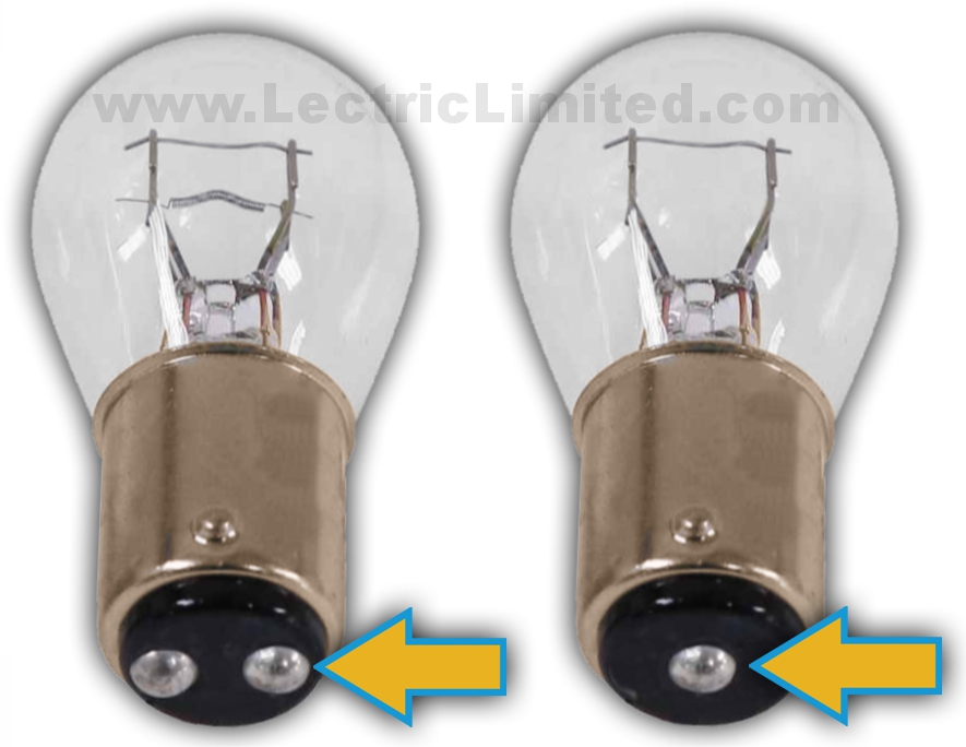
Check your bulbs!!! You probably have the wrong bulb(s) in your lamp sockets.
If you can see 2 contacts in the base of the lamp socket, then you NEED to use the correct 2-contact light bulb (not a single contact bulb). The reason there are 2 contacts is because some bulb sockets have a hi-low filament and some sockets (especially on Corvettes) are not grounded. With non-grounded lamp sockets, an additional wire/contact (ground) is used. If you attempt to use a single contact bulb in 2 contact lamp socket it will cause an instant short to ground and blow a fuse. This usually happens as soon as you open your door.
For some cars, we offer complete bulb kits with all the proper bulbs. See our online catalog for your application.
My 1965 GM turn signal switch doesn’t cancel properly. What’s wrong?
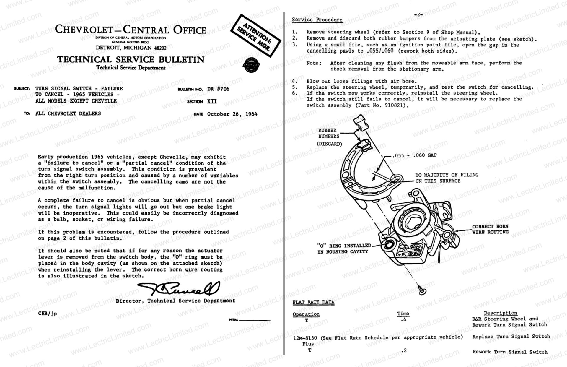
If you purchased the turn signal switch from Lectric Limited or one of our distributors, for your 1965 GM vehicle (all models except Chevelle) there is probably nothing wrong with the turn signal switch. There was a T.S.B. (technical service bulletin) issued by GM to address, and show how to correct, this potential problem. Please note that modifying your turn signal switch will void your warranty. We do not have any additional information to provide about this switch.
Alarm On/Off Switch on a 1977-82 GM vehicle does not arm in the proper position. Why not?
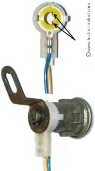
We have been made aware that occasionally customer’s experience a problem when installing reproduction (and even NOS GM) Alarm On/Off Switches. After a new alarm switch is installed, when the door is locked and the key removed, the alarm should be activated (turned-on). But some customers state that while turning the key to lock their car everything works properly (alarm has turned-on) until the final fraction of a turn – when the key is in the position to be removed, that the alarm turns off again.
Our research has found no documentation as to what the GM assembly line workers did to correct this problem. But we do have a possible solution that can be found in the inner piece of the switch (yellow part on our switch below) that goes over the lock cylinder shaft. To modify this switch, using an Exacto knife or small blade to carefully remove (shave-off) a very small amount of the plastic in the area(s) shown below in red.
Should you modify your switch? If so, from which side should you remove material? How much material to remove? These questions would be up to you to decide, depending on your particular switch. In any case, if you do decide to modify your switch, remove only a very small amount of material at a time (about 1/1000”). If you remove too much material, the switch will be ruined. PLEASE NOTE: We are providing this instruction as a courtesy to those who experience a problem. If your alarm switch needs to be modified to function properly with your particular lock cylinder, we are not responsible for the modification. We have no further information to provide.
Do You Sell . . . ?
Do you sell individual connectors, terminals, fuse link wire, resistance wire or harness clips? Our #1 Asked Question!

Typically, we do not.
We frequently receive calls from customers looking to purchase repair parts for their wiring harnesses, with requests like, “I just need an ignition switch connector,” “I need a single terminal for the headlight switch,” or “Can I get a 5-inch piece of orange fuse link wire?” These requests happen so often that we’ve had to clarify on our website and phone system that, aside from the limited repair components listed in our online catalog, we do not sell wiring harness repair parts.
So, why don’t we sell repair components? Occasionally, we’ve tried offering individual repair parts, but we found it detracts from our core business—selling complete wiring harnesses. The research involved in cross-referencing, verifying, and ensuring the availability of these components is time-consuming. For obsolete and discontinued components, each part sold means one less harness we can produce, and this quickly becomes more costly than the part itself. Additionally, customers are often unhappy when a small plastic connector costs $20 plus $7 shipping. We’ve also encountered situations where a customer orders the wrong part, then wants to return it, which involves inspecting for damage and re-shipping. While we aim to assist our customers, offering repair parts has consistently led to complications.
For these reasons, we kindly ask that you refrain from calling or emailing us for individual components, as we will have to give the same response and hope you understand why.
As an alternative, if you prefer to repair your wiring, we suggest purchasing an old harness from eBay to remove the components you need. Keep in mind that all the components required to repair your old harness are included with our new wiring harnesses. Additionally, some parts may still be available through electronic suppliers, but you will need to research these options independently, as we do not have specific recommendations for sources.
Do you sell the non-adhesive harness tape so I can re-wrap my harness?
While we don’t recommend repairing an old harness, if you choose to or simply want to give your old wiring harness a refreshed appearance, we offer three widths of the correct non-adhesive, black vinyl, wiring harness wrapping tape. Don’t use adhesive-backed electrical tape, as the heat in your engine compartment can cause the adhesive to “melt”, leading to the tape unraveling and dirt sticking to the adhesive.
The non-adhesive tape we offer, which we also use to wrap all of our wiring harnesses, adheres to itself without the need for adhesive. This type of tape was used on factory-original harnesses.
Lectric Limited offers wiring harness repair tape in a 100 ft. roll and is available in (3) widths: 3/4″, 1″ or 1-1/4″. The 3/4″ roll is recommended when wrapping a small diameter harness (10 wires or less, for example). Larger diameter rolls can be used when wrapping a dash harness or similar, large diameter wiring harnesses.
Do you sell individual T-3 headlight bulbs?
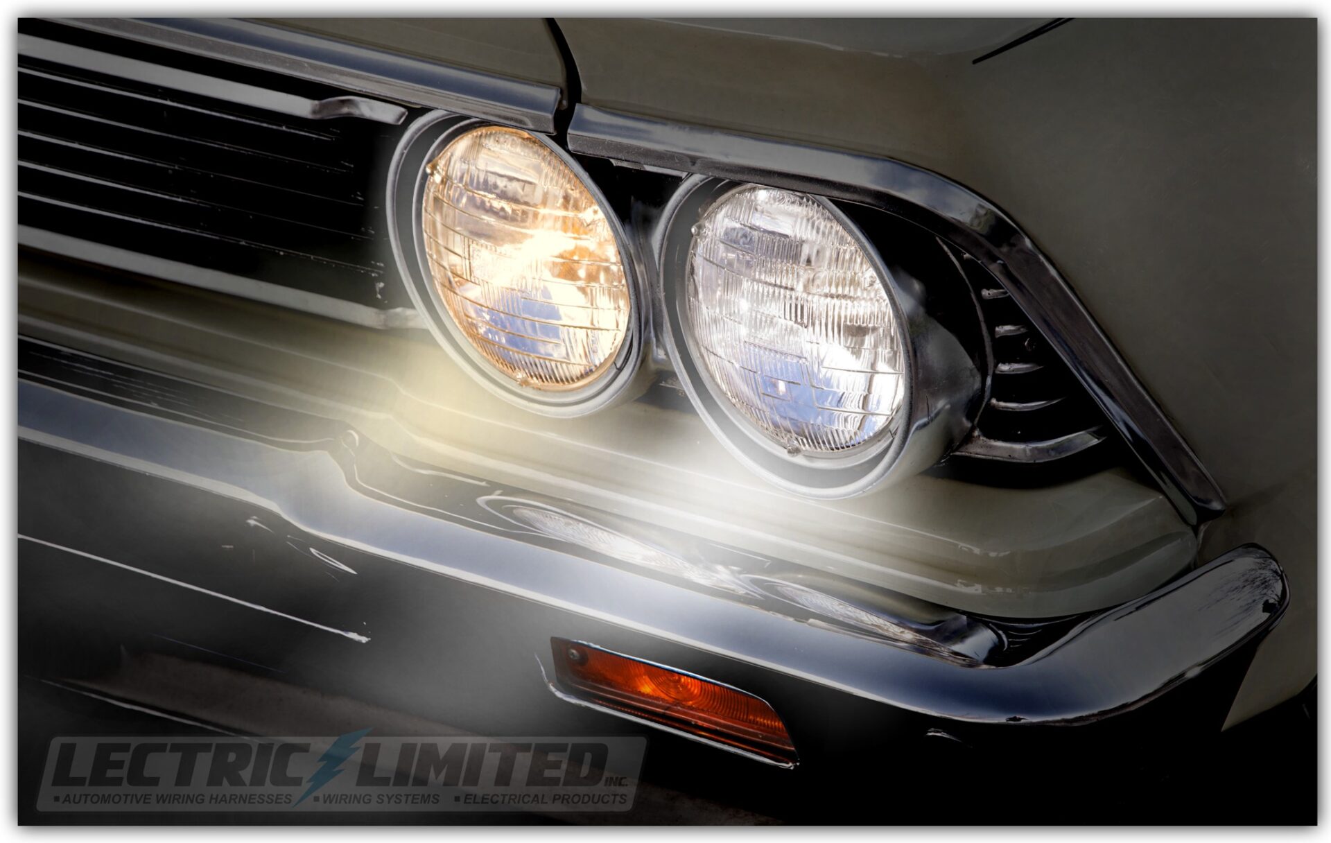
We do not. T-3 headlight bulbs are only available in 2 or 4 bulb (complete) boxed sets, as originally installed.
But, even if they were available separately, we would not recommend replacing only one bulb. Our new T-3 bulbs are brighter than the original, yellow cast bulbs. You would instantly notice the difference between the old/original T-3 headlight bulb and the new bulb when placed side-by-side. Photo on the right is a simulated example of what we’re describing. Bulb on the right is Lectric Limited’s T-3 bulb.
T-3 is a registered trademark of Lectric Limited, Inc.
Do you sell individual spark plug wires?
We do not. Our spark plug wires are only available in complete sets, which include the coil wire, di-electric grease pack and installation instructions.
Do you sell spark plug wires with the exact script (text printed on wire) that I need?
Lectric Limited currently manufactures over 2,500 different spark plug wire sets for a wide variety of vehicles, including those from GM, GMC, Chrysler, AMC, Packard, Studebaker, and Holden (Australian models). For those seeking spark plug wires that fit better than standard auto parts store options and offer a period-correct appearance—without concern for car show judging—we recommend our REPLACEMENT spark plug wire sets. If this is your preference, this FAQ will not be relevant to you. Alternatively, for those who want spark plug wires that fit, function, and look exactly as they did originally (and are concerned about car show judging), we highly recommend our REPRODUCTION spark plug wire sets.
DATE-CODE SCRIPT:
For the purist or restorer, we offer reproduction date-coded spark plug wires. But what are “date coded” wires? Beginning in January 1961, spark plug wire manufacturers started printing a manufacturing date on their wires for internal identification and quality control purposes. Note: Vehicles from GM, Chrysler, and AMC built before January 1961 did not use date-coded wires. Research has shown that most vehicles typically had wires installed with a date code ranging from 1 to 4 quarters prior to the vehicle’s build date—equivalent to 1 to 12 months. Lectric Limited’s spark plug wire sets are date-coded to either the first quarter (1-Q) or third quarter (3-Q) of each year, starting in 1961.
Does Lectric Limited offer 2nd & 4th quarter date codes?
We do not. However, from a car show judging standpoint, this is not necessary due to the wide time range (1 to 12 months) mentioned earlier. For more information about date-coded spark plug wires, please refer to our detailed description.
Non-Date Coded Wires:
Some of our reproduction spark plug wire sets are described as “REPRODUCTION BUT NOT DATE CODED.” What does this mean? It means that although these wires were originally date-coded, we’ve determined that there is insufficient demand to justify the significant investment in tooling, production, materials, and warehouse space necessary to produce them. The costs involved in adding a date code to these wires would substantially outweigh the potential return.
CYLINDER # SCRIPT:
Does Lectric Limited print the cylinder number on their spark plug wires?
We recognize that on certain year/make/model vehicles, the cylinder number was originally printed on the spark plug wire. However, we do not print the cylinder number on our wires. Why not? Similar to the non-date coded wires mentioned above, we have concluded that there is not enough demand to justify the necessary investment in tooling, production, material outlay, and warehouse space. The costs associated with adding the cylinder number to each wire set would significantly exceed the potential return.
For those who prefer the cylinder number on their wires, some customers have used small rubber stamps to print the cylinder number themselves.
Do you sell the metal braiding that goes around my big block spark plug wires?
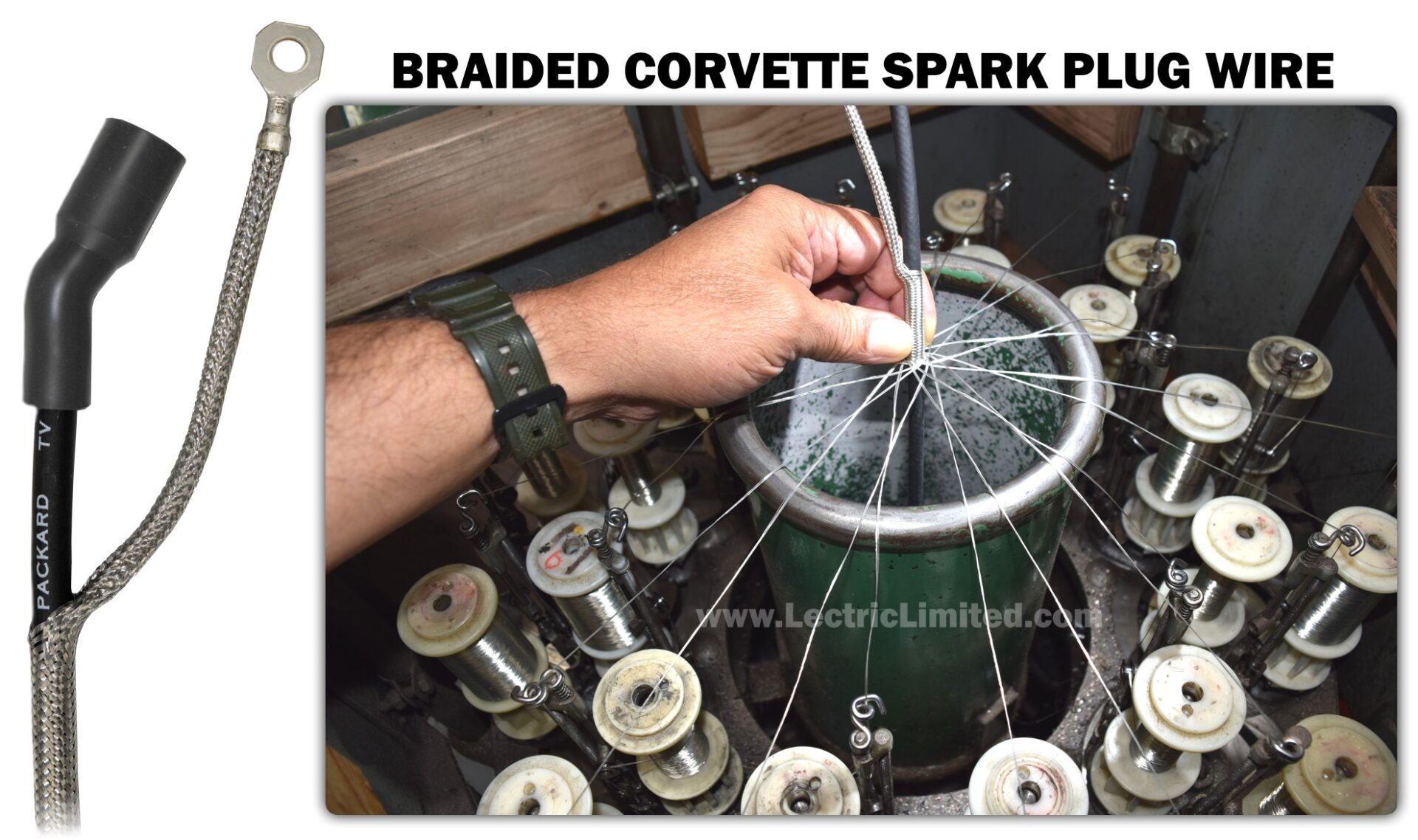
We do not. It’s not possible. The braiding, designed to prevent ignition noise from being received by your radio, must be applied by a braiding machine directly onto the spark plug wire. It cannot be slid on or would be very difficult to do so. Machined braided wires are the only way to provide a tight, no-slip application.
Do you sell the fiber optic cable separately? Explain the 68-71 Corvette fiber optic system.
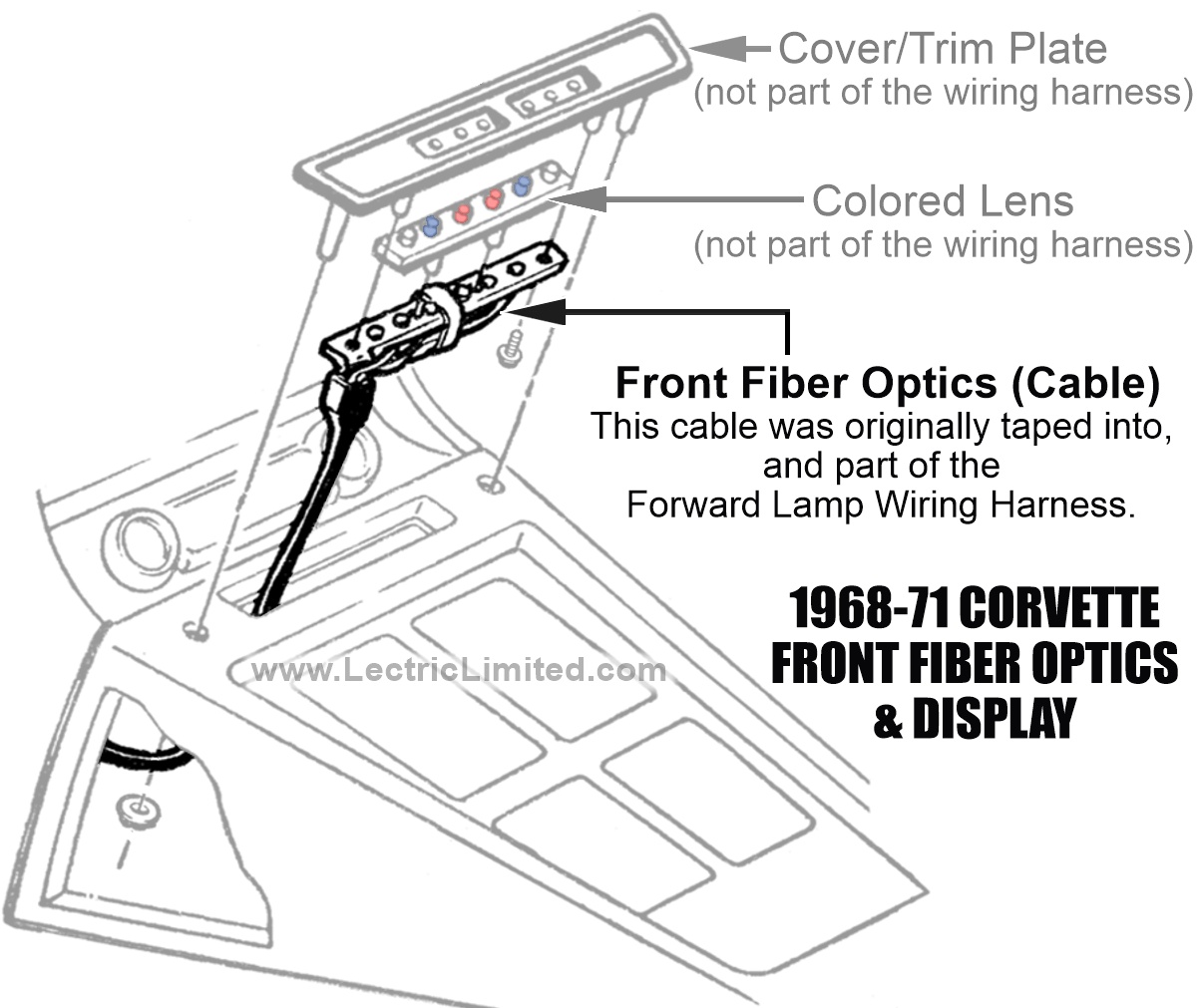
The 68-71 Corvette fiber optic system was an innovative lighting feature that enhanced the car’s interior by providing visual indicators for various external lights.
This system used fiber optic cables to transmit light from the exterior lamps—such as turn signals, headlights, and parking lights—into the dashboard, allowing the driver to easily see whether these lights are functioning.
Key Features:
- Visual Indicators: Small, colored light filters on the dashboard illuminate when the corresponding exterior lights are activated, serving as a quick reference for the driver.
- Streamlined Design: The use of fiber optics allows for a cleaner and more integrated look in the dashboard, eliminating the need for bulky switches or indicators.
- Enhanced Safety: By providing clear visual feedback about the status of external lights, the system helps ensure that all lights are functioning properly, improving safety on the road.
Operation:
- When a driver activates a turn signal or headlights, the corresponding exterior lamp sends light through the fiber optic cables.
- The dashboard indicators light up, signaling to the driver that the external lights are operational.
Originally, the front fiber optic cable was integrated into, and part of, the forward lamp wiring harness and the rear fiber optic cable was integrated into, and part of, the rear body wiring harness. When you purchase Lectric Limited’s 1968-71 Corvette Front Light Harness or Rear Body Harness, you will receive new fiber optic cables that are integrated into these harnesses – just as they were originally manufactured.
However, if you only want to replace the fiber optic cable, not the entire wiring harness, we do offer both the front and rear fiber optic sub-assembly as a repair item. This sub-assembly would be installed/routed along-side the forward lamp wiring harness (for the front), and along-side the rear body harness (for the rear). You can affix the fiber optic sub-assembly to the wiring harness with either non-adhesive harness tape (which we sell) for a more original look, or by using plastic zip ties.
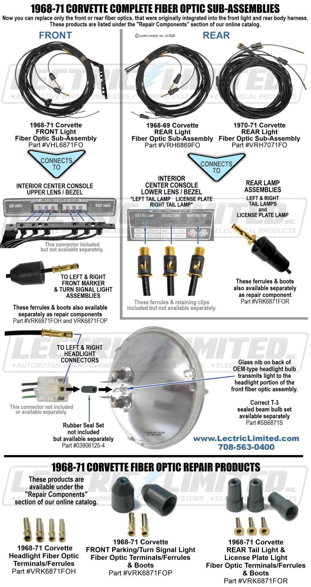
F.Y.I. (For Your Information)
I’m confused on terminology. What is the terminal? What is the connector?

Using the correct terminology makes a big difference when talking to someone about your car’s electrical system. Whenever discussing your vehicle’s electrical needs, please take into consideration what you’re talking about.
The TERMINAL is the metal piece (usually brass or plated brass) that gets crimped to the wire(s). It is not called a ‘connector’, a ‘prong’, a ‘clip’, or an ‘end’. The CONNECTOR is the piece that the terminal is inserted into, usually made of plastic or rubber.
How do I remove a terminal from its connector?
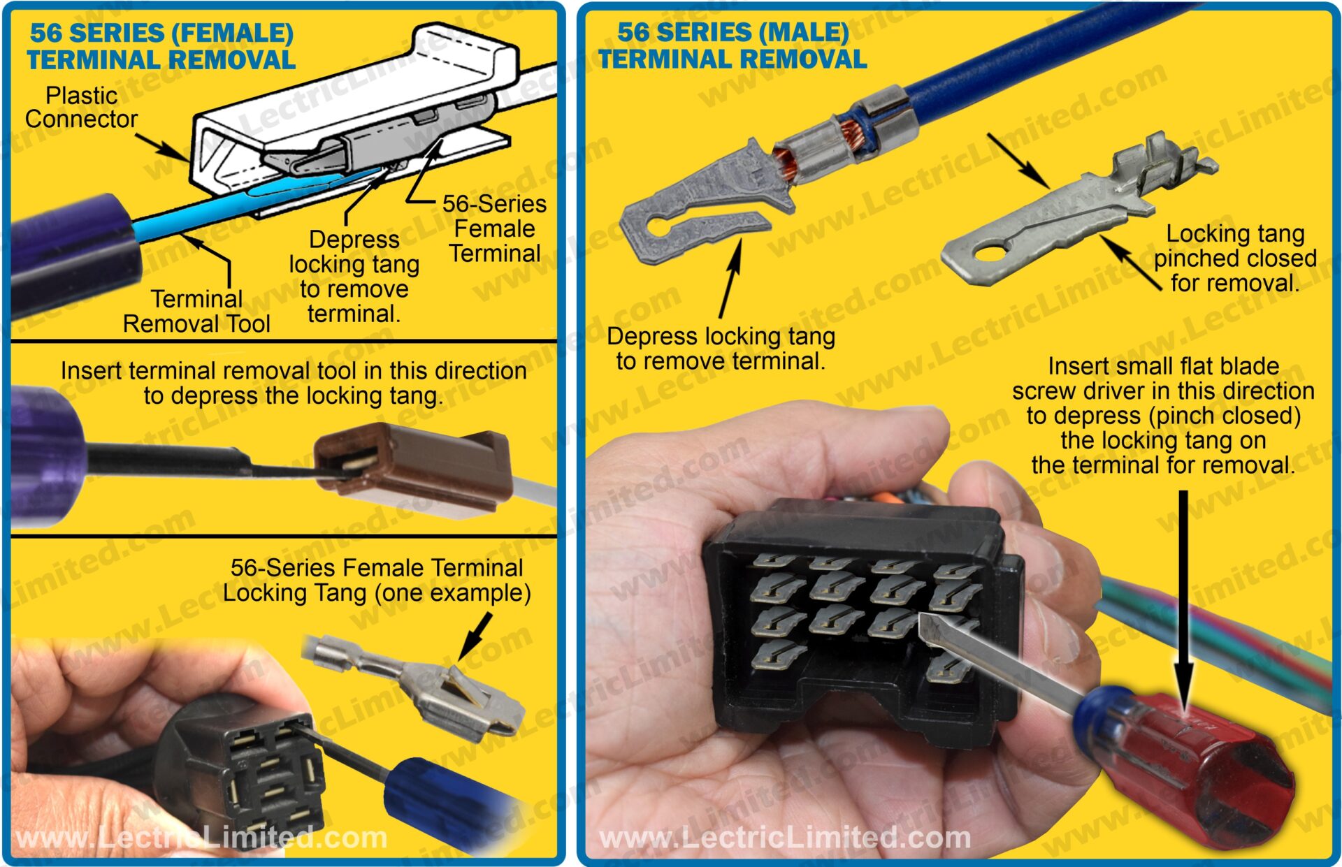
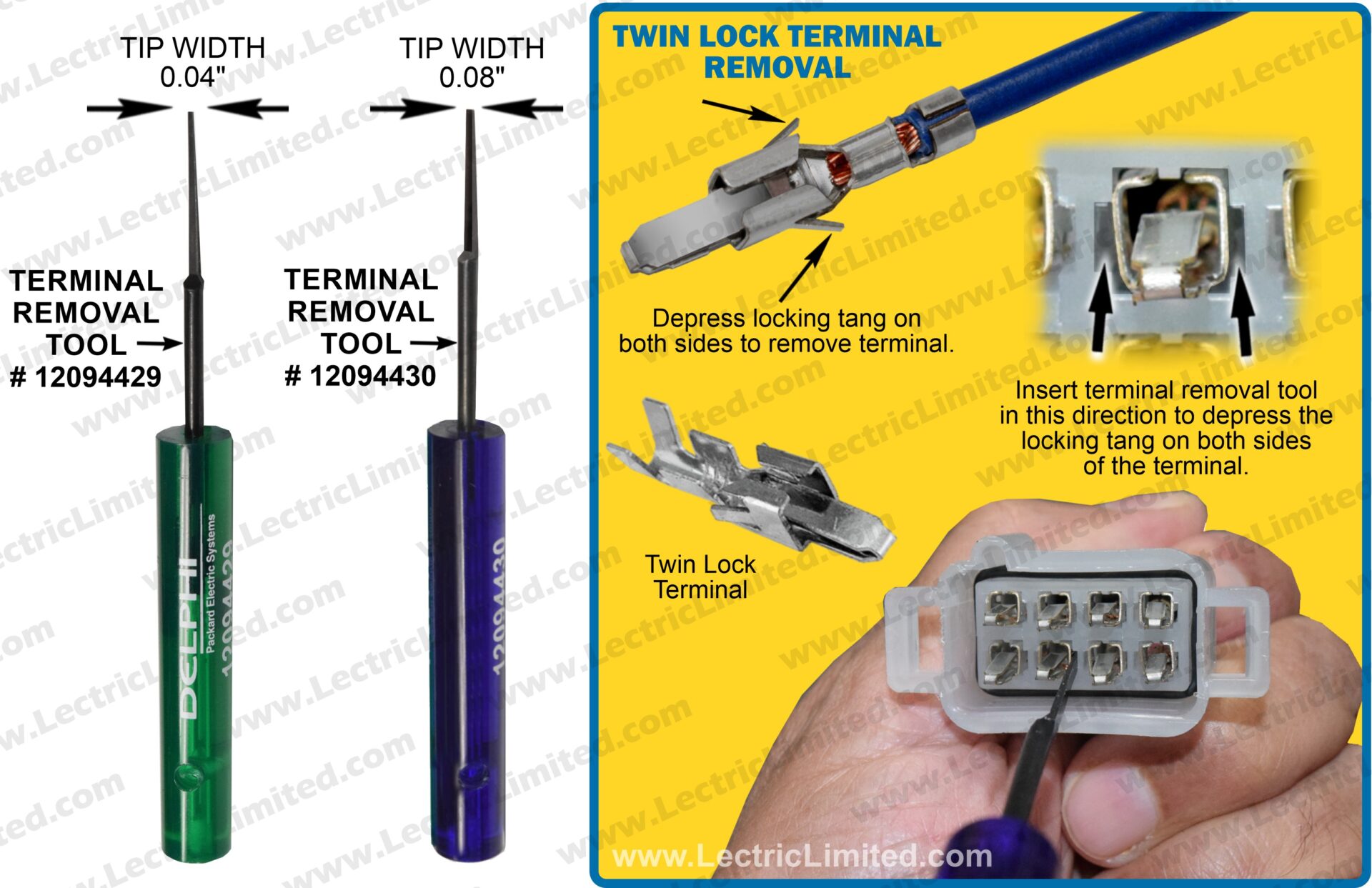
Sometimes, it is necessary to remove an automotive terminal from its connector. The process can be a bit tricky but can usually be done with a few tools and care. Here’s how to do it:
Tools Needed
- Small Flathead Screwdriver: For depressing the terminal’s locking tang. Useful on 56 series female terminals.
- Terminal Removal/Release Tool: For depressing the terminal’s locking tang. Useful on 56 series male and twin lock terminals. Lectric Limited sell (2) types of hardened steel terminal removal tools. #12094429 has a .04″ tip width and #12094430 has a .08″ tip width. The .08″ version is the most popular.
- Needle-Nose Pliers: For gripping the terminal if necessary.
Steps to Remove the Terminal
- Disconnect the Battery: Always disconnect the negative terminal of the battery before working on automotive electrical components to avoid shorts or shock.
- Release the Locking Tang: Use a very small flathead screwdriver or proper terminal removal/release tool to gently depress the locking tang. This may need to be done while gently pulling on the wire attached to that terminal.
- Be careful not to break the plastic connector, the terminal, or the terminal’s locking tang. These may be needed for reassembly.
What do the wire color abbreviations mean on a wiring diagram?
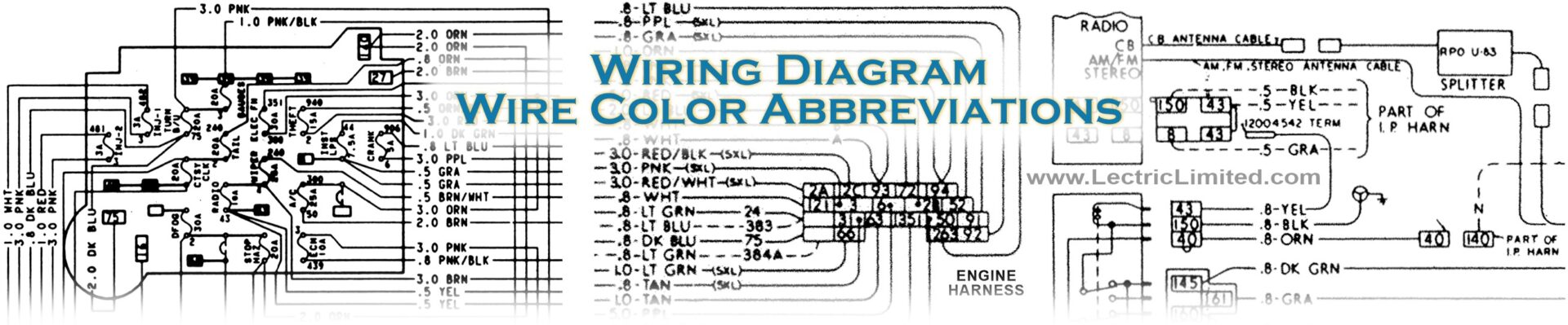
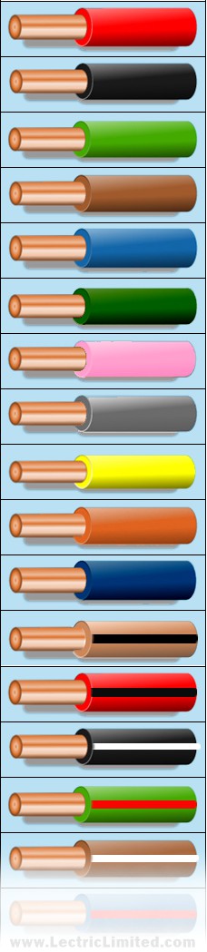
There was no consistency being used in abbreviating wire colors. For example, on one wiring diagram, ‘B’ would mean a black wire. On another diagram, ‘BLK’ was used to abbreviate a black wire. Here are other abbreviations.
- B = Black
- BK/WHT = Black w/White Stripe
- BLK = Black
- BLK/ORN = Black w/Orange Stripe
- BLK/PNK = Black w/Pink Stripe
- BLK/RED = Black w/Red Stripe
- BLU/BLK = Blue w/Black Stripe
- BLU/RED = Blue w/Red Stripe
- BRN = Brown
- BRN/WHT = Brown w/White Stripe
- DBL = Dark Blue
- DG = Dark Green
- DK BLU = Dark Blue
- DK GRN/YEL = Dark Green w/Yellow Stripe
- DK GRN/WHT = Dark Green w/White Stripe
- DK GRN = Dark Green
- GRA = Gray
- GRN/BLK = Green w/Black Stripe
- GRN/RED = Green w/Red Stripe
- GY = Gray
- LBL = Light Blue
- LG = Light Green
- LT BLU = Light Blue
- LT BLU/RED = Light Blue w/Red Stripe
- LT BLU/BLK = Light Blue w/Black Stripe
- LT GRN = Light Green
- NAT = White (Natural)
- OR = Orange
- ORN = Orange
- P = Pink
- PNK/BLK = Pink w/Black Stripe
- PNK = Pink
- PPL = Purple
- PPL/WHT = Purple w/White Stripe
- R = Red
- RED/BLK = Red w/Black Stripe
- RED = Red
- RED/WHT – Red w/White Stripe
- T = Tan
- TAN/BLK = Tan w/Black Stripe
- TAN = Tan
- TAN/RED = Tan w/Red Stripe
- TAN/WHT = Tan w/White Stripe
- V = Purple (Violet)
- WHT/BLK = White w/Black Stripe
- WHT = White
- Y = Yellow
- YEL = Yellow
- / = Stripe (ex. B/P = Black wire with a Pink Stripe
- // = Double Stripe (ex. P//B = Pink wire with a double Black Stripe
Spark Plug Wires: Is it better to use solid core, carbon core, 7mm, 8mm, or something else?
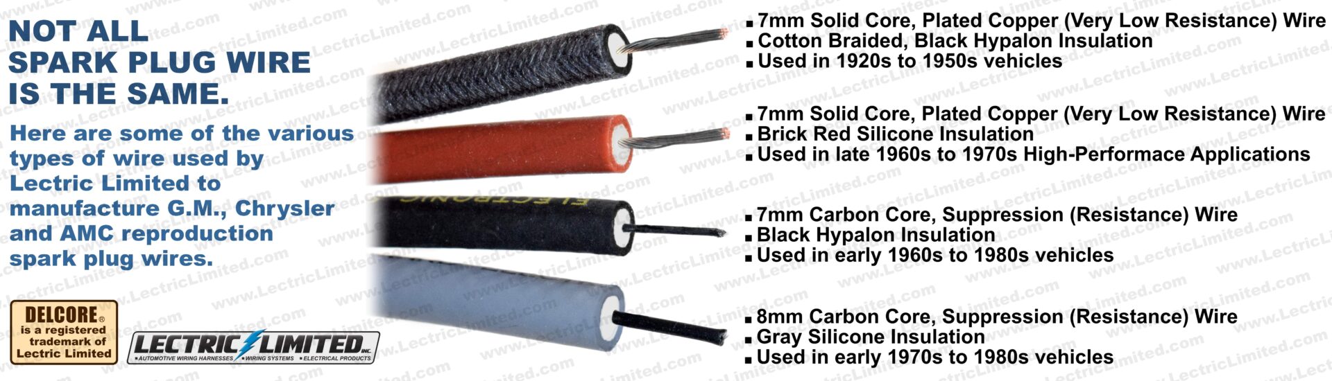
Not all spark plug wire is the same. It’s important to choose spark plug wires that are compatible with your vehicle’s year/make/model ignition system to ensure optimal performance. Lectric Limited manufactures the correct wires that were originally on your vehicle. See our online catalog for your application.
7mm Cotton Braided, Solid Core – Automotive manufacturers began using solid core spark plug wires in the 1920s. These wires were typically made of solid or plated/tinned copper and were popular for their low electrical resistance and ability to provide a strong spark. Solid core wire has a very low resistance of around 0.5 to 1.5 ohms per foot. This low resistance allows for optimal current flow to the spark plug, making them ideal for high-performance applications. However, keep in mind that solid core wires can cause radio frequency interference (RFI) since they lack the suppression features found in resistor wires.
7mm Brick Red Color, Solid Core – Brick red colored (silicone insulation) high-performance spark plug wires were commonly used in some muscle cars and performance vehicles during the late 1960s and 1970s, particularly from manufacturers like General Motors and Chrysler.
7mm Carbon Core – Due to the significant radio frequency interference (RFI) produced with solid core wires, many manufacturers transitioned to carbon (fiber) core or resistance wire in the early 1960s. The move away from solid core wires became more pronounced in the late 1970s and 1980s as vehicles increasingly adopted electronic ignition systems and emissions control technologies. Carbon core spark plug wire typically has a resistance of around 1,000 to 10,000 ohms per foot, with most common applications falling between 2,000 and 5,000 ohms per foot. The carbon core provides a level of resistance that helps reduce RFI that can affect not only the radio but also modern electronics like electronic fuel injection, computer-controlled ignitions, etc. making these wires suitable for street applications where noise reduction is important.
8mm Carbon Core – Automotive manufacturers began using 8mm spark plug wires in the late 1970s and early 1980s. This shift was largely driven by the demand for improved performance and better resistance to heat and electrical interference. Many manufacturers, including GM, Ford, and Chrysler, adopted 8mm wires during this period, especially for high-performance and muscle cars. By the mid-1980s, 8mm wires became more standard in a variety of vehicles.
Should I use dielectric grease on all my connectors & terminals?
Dielectric grease is an electrical insulator, meaning it does NOT conduct electricity. Its primary function is to inhibit high-voltage arcing to ground, making it especially beneficial when applied to the interior of spark plug wire boots. This helps prevent unintended spark discharge along the interior and exterior of the boot. Additionally, when used on spark plug wires, dielectric grease minimizes the risk of the rubber boot adhering to the ceramic insulator of the plug, facilitating easier removal. Beyond ignition systems, dielectric grease can also serve as a protective barrier against moisture, dirt, road salt, and aid in preventing corrosion when applied AFTER establishing a metal-to-metal terminal connection.
DO NOT apply dielectric grease to an oxygen sensor connector. Many times, the sensor is vented through the wiring. Over time, the grease may contaminate the senser and it may cease to function.
What is a fusible link and what do I do if it “blows”?
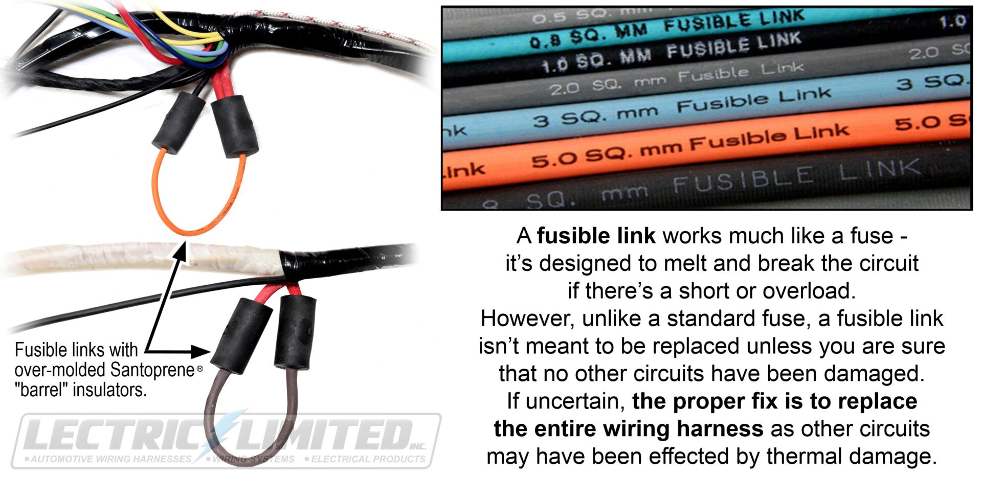
A fusible link functions much like a fuse, interrupting current flow by melting internally when exposed to excessive current from a short or overload. However, unlike a standard fuse, a fusible link is not intended to be replaced in the field. If a fusible link opens, the proper corrective action is to replace the entire wiring harness, since heat damage may have spread to adjacent wires and circuits within the harness.
General Motors began incorporating fusible links into wiring harnesses in the mid-1960s as vehicle electrical systems became more complex and required dependable protection for high-amperage circuits such as the starter, alternator, and main power feeds. Over time, automakers transitioned to fuses, which provided the same protection while being easier and less costly to service.
A common question we hear is: “If my fusible link has failed/blew, can I just replace it instead of the entire wiring harness?” The answer is no—the complete harness should be replaced if you are not sure if other circuits were damaged. This is because additional circuits may have been damaged by heat, and proper fusible link wire with the correct gauge and high-temperature insulation is generally not available for individual service replacement. Furthermore, the splice must be properly insulated, which originally required an over-molded Santoprene® “barrel” insulators. In the absence of factory tooling, a suitable equivalent insulator would need to be applied over the repair.
Important: Before installing a new harness, the root cause of why the fusible link failed/blew must be identified and corrected to prevent repeat damage to the wiring harness.
What is the purpose of radio capacitors in my old car?
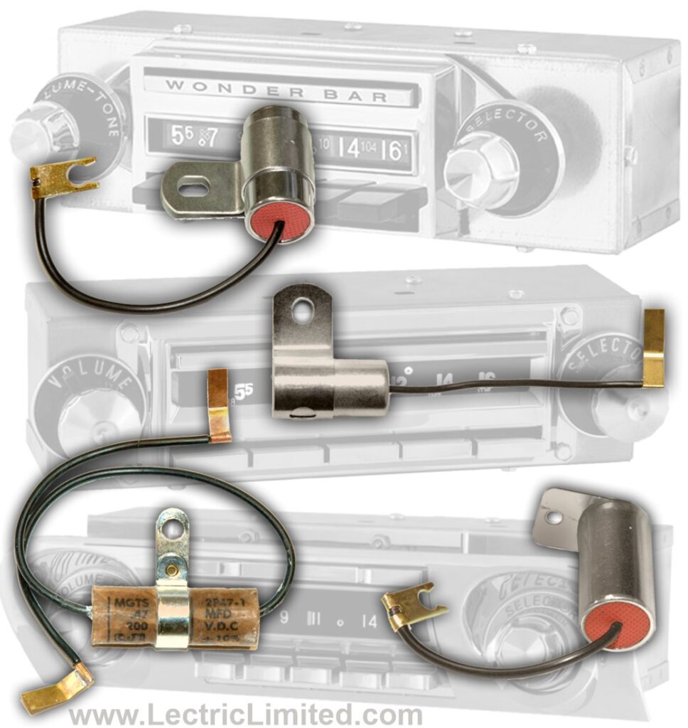
Ignition systems, charging systems and electrical devices can create magnetic pulses that are of the same frequency range as AM radio, resulting in electromagnetic interference (EMI) or radio “noise”. The purpose of radio capacitors was to filter-out this noise. These radio noise suppression capacitors divert this noise to ground so it isn’t heard through the radio’s speakers as an annoying buzz or whine. The sound’s pitch will usually rise & fall as the engine RPM changes. 99% of the purpose of radio capacitors was to eliminate buzzing noise through the speakers. But the capacitors also function to eliminate fluctuating, or ‘popping’ gauges.
Radio capacitors were installed in any area of the vehicle that could create radio “noise”. Some of these locations were the: ignition coil, voltage regulator, ammeter, ignition switch, turn signal switch and parking brake alarm switch.
You may ask, ‘Do I need to have these capacitors’? Well, they do not affect the integrity of the wiring. But without functioning capacitors, the results can be annoying – ie. ‘popping’ gauges. (Note: Capacitors were not installed at the factory if your vehicle did not come equipped with a radio.)
Lectric Limited offers various radio capacitors. See our online catalog for your application.
Which is better, a 3-wire or 1-wire alternator? Why don’t we make wiring (or wiring conversions) for 1-wire alternators?

The use of a 1-wire (single wire) alternator, to replace a 3-wire alternator, has been marketed as the ‘hot setup’, and unfortunately are becoming increasingly popular. However, being popular doesn’t mean being better. In our opinion, a 1-wire alternator should NOT be used in cars or trucks (with the possible exception of some race applications).
For most applications, and for 99% of our customers, the advantages of a 3-wire alternator (CS series or SI series) far outweigh a 1-wire conversion. Here’s why…
| OPTIONS | 3-WIRE | 1-WIRE |
| Designed specifically for general car/truck use? | Yes | No |
| Originally designed specifically for race applications? | No | Yes |
| Should be used if your vehicle has any device that draws power from the charging system (ie headlights, tail/brake lights, turn signal lights, driving lights, radio, power accessories, air conditioning, electric fan, blower motor, etc.)? | Yes | No |
| Ignition system is not deprived of voltage while alternator is charging your battery? | Yes | No |
| Can operate a Warning Light (‘idiot light’) on the dash? | Yes | No |
| Can read ‘Voltage Sensing’ remote from the alternator? | Yes | No |
| Available at nearly all auto parts stores and parts suppliers? | Yes | No |
| Generates electricity at any engine R.P.M.? | Yes | No |
| Best suited for battery longevity due to alternator’s charging characteristics? | Yes | No |
| Minimal knowledge required for wiring installation? (That being said, there is no wiring knowledge required if you upgrade your original generator/alternator to a 3-wire alternator using one of our ‘Alternator Conversions’. See our online catalog for availability.) | No | Yes |
| Internal replacement parts readily available if alternator needs to be serviced? | Yes | ? |
| Less expensive? | ? | ? |
| If you decide to upgrade your generator/alternator from original, what does Lectric Limited recommend? | Yes! | No |
The 1-wire alternator is not new technology*. It has been around about as long as the 3-wire alternator. Knowing this, if the 1-wire alternator would have worked better on cars/trucks, then over the years, GM could have saved a fortune in wiring by converting to a 1-wire alternator. But GM did not compromise electrical system performance in this area. They did spend more money for engineering and wiring to install a 3-wire alternator which will deliver best performance. And as we have shown, there virtually no advantages to using a 1-wire alternator in a car or truck.
It is because we don’t recommend using a 1-wire alternator that we do not make wiring harness conversions for them.
* GM/Delco did manufacture a 1-wire alternator, but it was not for use on cars or trucks.
Explain the 1953-55 Corvette radio noise suppressor at the distributor cap.
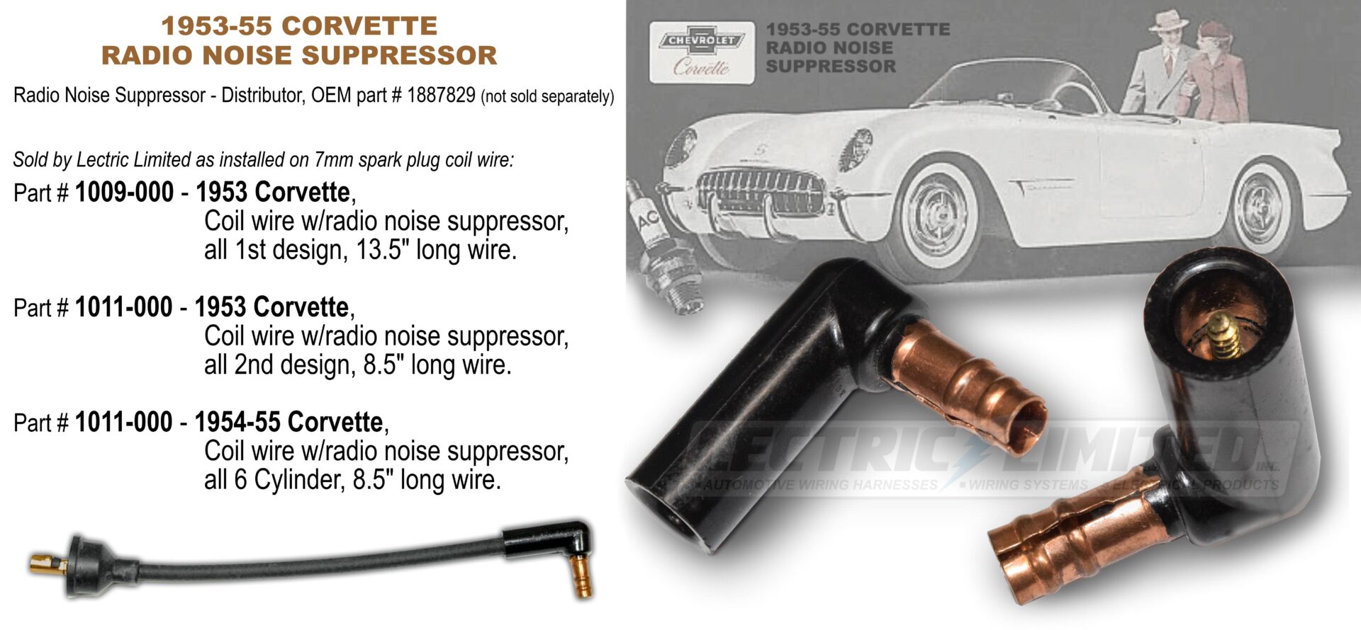
Many enthusiasts may not realize that all 1953–55 six-cylinder Corvettes were equipped with a factory-installed radio noise suppressor. This Bakelite, elbow-shaped component screwed into the coil wire and was positioned between the coil wire and the distributor cap.
What is a radio noise suppressor? A radio noise suppressor, often referred to as capacitor or condenser, was used in older cars to reduce electrical noise that could interfere with AM band radio reception. This noise typically originated from the ignition system and other electrical components. While this suppressor/capacitor was not critical for engine operation, it was important for improving radio clarity.
Interestingly, the part number for the 53-55 Corvette suppressor/capacitor does not appear in standard Chevrolet or Corvette Parts and Accessory Manuals. It is, however, documented in the 1953–1955 Corvette Radio Service and Shop Manual. On the final page, it is listed as “SUPPRESSOR, Distributor….1887829*”. An asterisk next to the part number indicates it was also used on other Chevrolet passenger cars and trucks.
Suppressor 1887829 is not available for purchase separately. However, Lectric Limited does offer this hard-to-find (NOS) suppressor as installed on their fully-assembled 7mm spark plug coil wire, as follows:
1953 Corvette – Part # 1009-000. Coil wire w/radio noise suppressor, all 1st design, 13.5″ long wire.
1953 Corvette – Part # 1011-000. Coil wire w/radio noise suppressor, all 2nd design, 8.5″ long wire.
1954-55 Corvette – Part # 1011-000. Coil wire w/radio noise suppressor, all 6 cylinder, 8.5″ long wire.
Note: Our 53-55 Corvette spark plug wire sets include a (standard) coil wire without this suppressor. This coil wire is adequate for the majority of customers. However, if you want the ultimate in authenticity, the coil wire with this suppressor is available separately, using the part numbers shown above.
Explain the 1963 Corvette Over Rev. (6500 redline) Warning System.
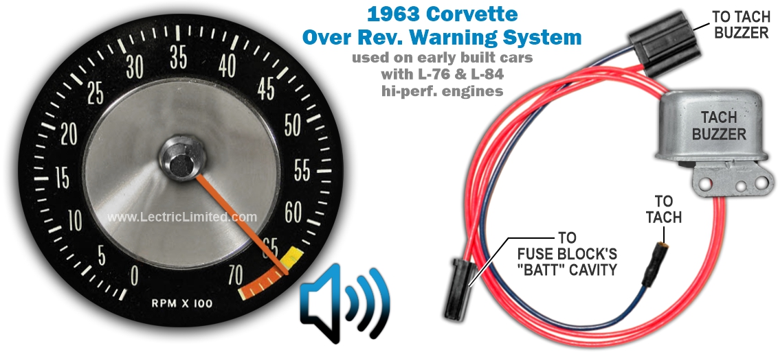
The Over Rev. Warning System came as standard equipment on early 1963 Corvettes (and possibly other vehicles) with L-76 and L-84 (340-260 H.P.) hi-performance engines, and a rare factory option on non-hi-performance 1963 Corvettes.
To protect the engine from being over rev’d, this system would sound a buzzer when the engine’s RPMs exceeded a predetermined factory setting (6500 RPMs).
The system consisted of a separate wiring harness and a special tachometer that included a buzzer. This system was soon discontinued by GM when they realized that the buzzer was not audible at high vehicle speeds. The visual warning (red zone) on the tachometer would remain.
Lectric Limited makes the wiring for this system, part #VTB6300.
Explain the 1967-69 GM Speed Warning System.
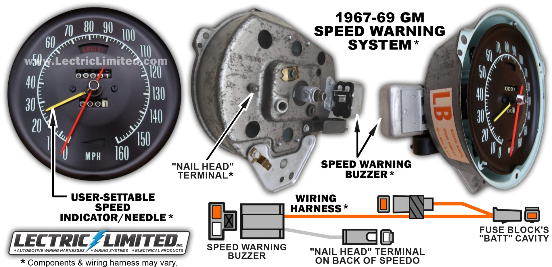
The 1967-69 Speed Warning System was an early automotive feature developed by General Motors to help drivers avoid speeding.
The system worked by allowing the driver to set/reset a speed indicator (needle) on the speedometer, by rotating a dial on the speedo or using a control knob under the dash. If the vehicle exceeded this pre-set speed, a warning light would illuminate and/or an audible buzzer/alarm would sound. This feature aimed to promote safer driving habits by alerting drivers when they were going too fast, particularly useful in areas with speed limits.
While it was a groundbreaking innovation at the time, the Speed Warning System eventually became obsolete as vehicles adopted more sophisticated technologies, not to mention that the buzzer was often drowned out by engine noise at high speeds.
Lectric Limited makes the wiring for the speed warning system. See our online catalog for your application.
Explain the 1972 GM Seat Belt Warning Buzzer System.
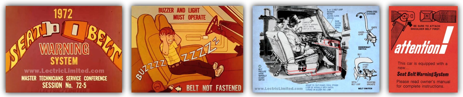
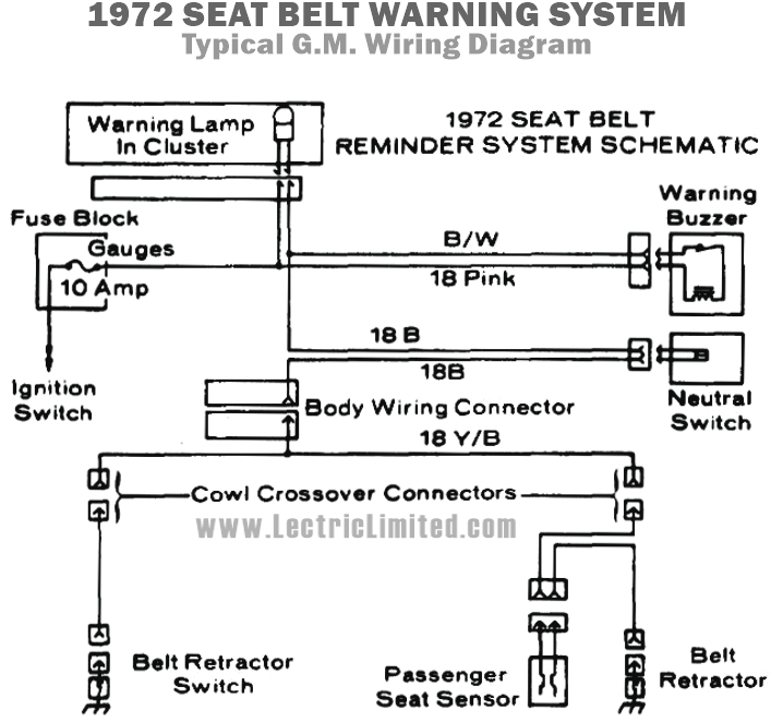
1972 introduced the seat belt warning buzzer to all GM vehicles. This buzzer was designed to audibly remind drivers to fasten their seat belt. Before purchasing a dash wiring harness and rear body wiring harness for your ’72, you must first identify how your car was manufactured.
Some 1972 early production vehicles did not have a seat belt warning system.
Other 1972 early production vehicles used the following to control the seat belt warning system:
- Indicator Lamp (illuminated for a few seconds)
- Timer (located behind dash)
If your vehicle is setup this way, you should purchase the Dash Harness, Rear Body Harness, and/or other electrical items for the “WITHOUT seat belt warning buzzer” application.
Most 1972 mid to late production vehicles used the following to control the seat belt warning system:
- Indicator Lamp (illuminated until seat belt pulled from retractor)
- Warning Buzzer (located behind dash, sounded until seat belt pulled from retractor)
- (1) Seat Switch (located in passenger side seat cushion)
- (2) Seat Belt Retractor Switches (located in each front seat belt retractor)
If your vehicle is setup this way, you should purchase the Dash Harness, Rear Body Harness, and/or other electrical items for the “WITH seat belt warning buzzer” application. NOTE: It is important to identify if your 1972 vehicle came from the factory with, or without the seat belt warning buzzer to avoid problems when rewiring your vehicle. Do not assume that because you don’t hear the buzzer, that your vehicle did not come with one. This buzzer was often removed because the sound was annoying.
Explain the 1974-75 GM Seat Belt / Starter Interlock System.
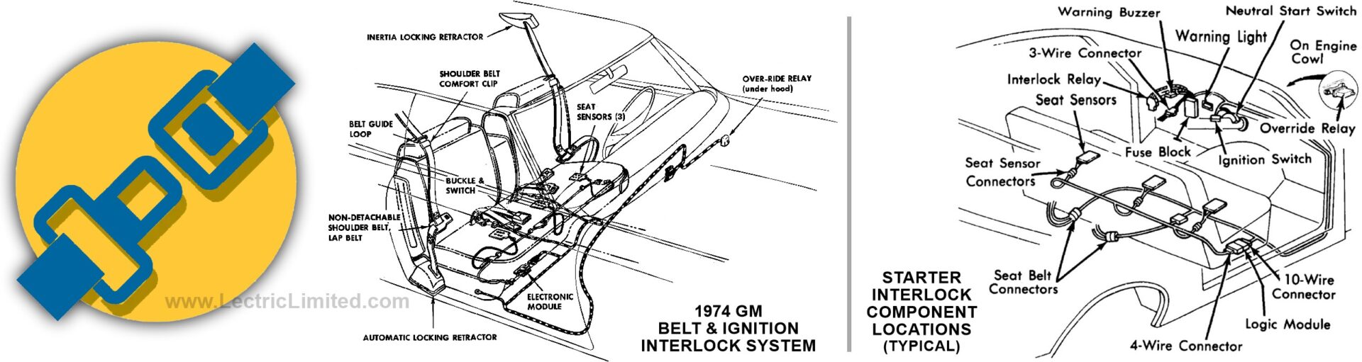
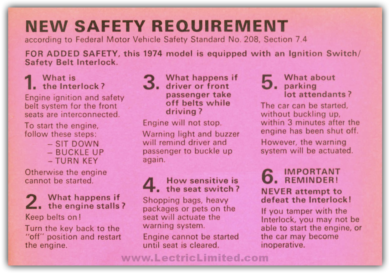
In the early 1970s, in an effort to get people to fasten their seat belts, the concept of a Seat Belt Interlock System arose. By definition, an interlock is an electrical-circuit arrangement that prevents a second operation from taking place until the first operation is completed. In the case of the seat belt interlock system, the car cannot be started unless the seat belts are fastened. But it goes beyond that. The seat belts must be fastened within a specific sequence. For example, the driver (and front seat passenger) must get into the car, close the door(s), sit down, and then fasten the seat belts. If the seat belts are not fastened, or if they are fastened in an incorrect order, the car will not start.
In 1974 model year, the Seat Belt Starter Interlock System was incorporated into every automobile to comply with Federal Motor Vehicle Safety Standard No. 208.
The following components were used for this system:
- A logic module (transistorized) that tracked the series of events.
- Two pressure sensitive front seat switches, a starter relay, a manual bypass relay (in case of a system failure and to make it easier for mechanics working on a car, a manual bypass button is located under the hood. Pushing this button allows 1 free start without needing to fasten the seat belt. Each additional free start requires that the button be pushed again).
- Two seat belt buckle switches.
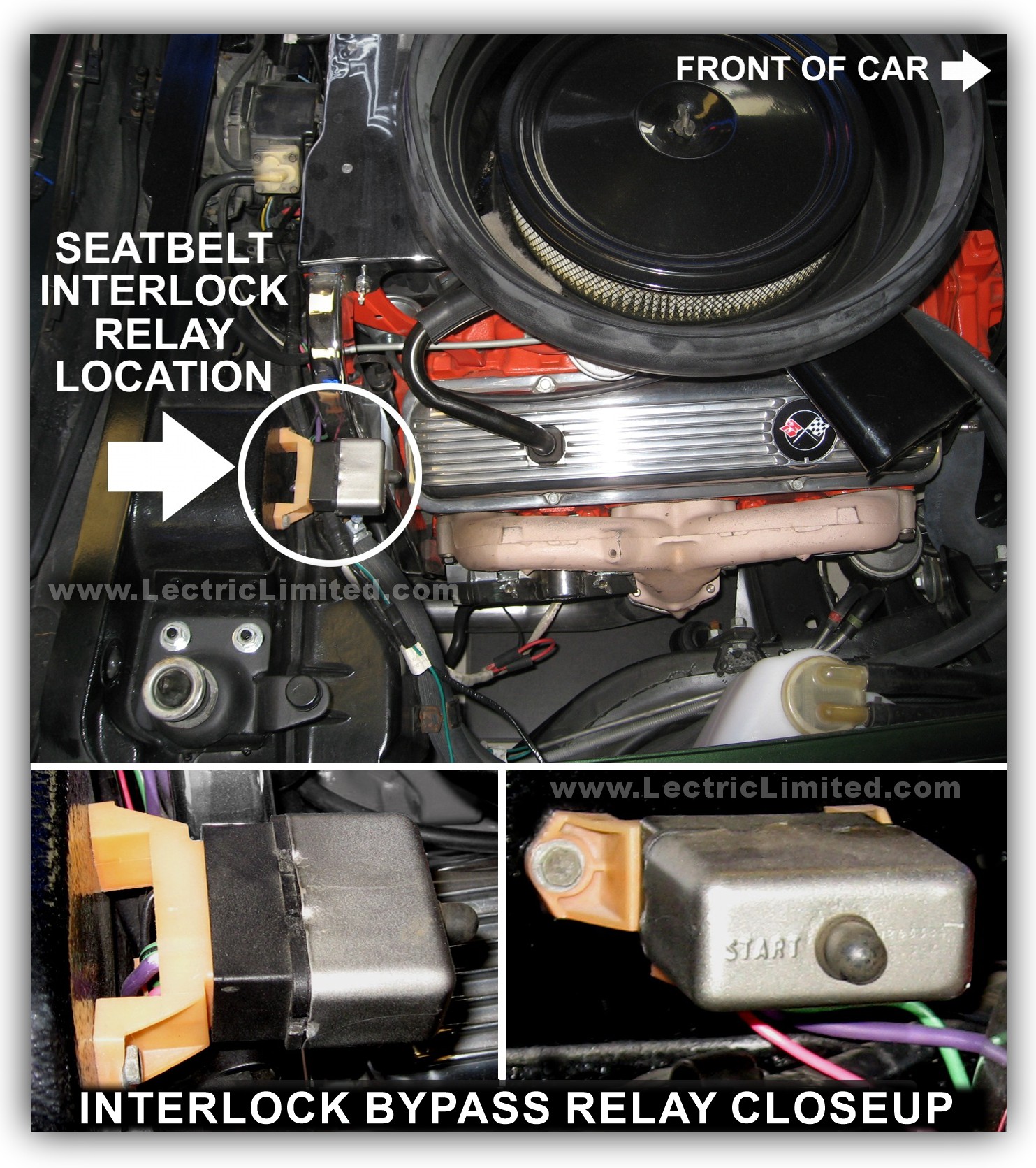
Although the warning buzzer and warning light were used to notify the driver to fasten his seat belt, they were not incorporated into the interlock system.
Soon after its implementation, frustrated and indignant citizens bombarded their congressmen to complain about the interlock device, and in early 1975, representatives quickly changed the law. The new law only required that a light and buzzer that would activate until the seat belts were fastened; doing away with the troublesome starter interlock system.
What Vehicles Incorporated This Interlock System?
All 1974, and early-to-mid 1975 vehicles.

Can I Bypass or Disconnect This System?
Although we cannot offer direct assistance in this area, there was documentation published as how to do so. For your convenience, we are providing the documentation from two Chevrolet Dealer Service Information Bulletins as well as information from another source.
Please Note, Lectric Limited makes no representations or warranties, express or implied, regarding the accuracy, completeness, or reliability of the information contained in these documents. All content is provided on an ‘as-is’ basis. Lectric Limited shall not be held liable for any errors, omissions, or consequences arising from the use or misuse of these documents, and offers no guidance, support, or assistance concerning its interpretation or application.
Can I Repair This System?
Repair of the seat belt interlock components is limited to its replacement. Testing the system requires the use of a special tester, which connects to the seat belt/starter interlock system at several points. About the only place that you are likely to find this tester, if you’re lucky, is at your local dealer. Because of this, repair and testing are best left to a dealer.
Can I Eliminate This System?
If you have a 1974 vehicle the answer is probably not. If you have a 1975 GM vehicle, it is possible. However, because the interlock system was integrated into several wiring harnesses, you will usually need to replace the Dash, Engine and Rear Body Harnesses with harnesses made for ‘WITHOUT seat belt interlock system’.
NOTE: If you’ve made the decision to completely rewire your 1975 vehicle, we strongly recommend that you purchase your wiring configured for ‘WITHOUT seat belt interlock system’. Doing so will allow you to eliminate all of the electrical components that are part of this system; components that may eventually fail, are no longer made, and are hard to find.
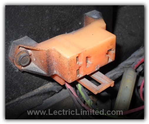
Can I Find Replacement Parts?
Lectric Limited offers exact reproduction wiring harnesses for 1974 vehicles with the interlock system. We also offer wiring harnesses for 1975 vehicles with or without the interlock system. However, the other components of the system (logic module, sensors, bypass device, and relays) have long been discontinued and are difficult to find. We do not know where to obtain these components but suggest a junk yard, swap meet, eBay, or a car club member.
How Do I Identify If My Vehicle Has/had This System?
All 1974 vehicles had the seat belt/starter interlock system. As for 1975 vehicles, unless you are the original owner or know the history of the vehicle, unknowing wiring modifications by previous owners or repair shops can make this identification difficult. We suggest trying to locate the specific components of the interlock system within the vehicle.
- Logic Module and Sensors often located behind or under the seats. (in Corvettes, it’s located behind the seats)
- Starter Interlock Relay mounted in console or under the dash. (in Corvettes, it’s mounted in the console)
- Manual Interlock Bypass Relay mounted on firewall or on the fender well. (In Corvettes, it’s mounted on the firewall as shown in the photo.)
Can I replace my regular (incandescent) light bulbs with LEDs?
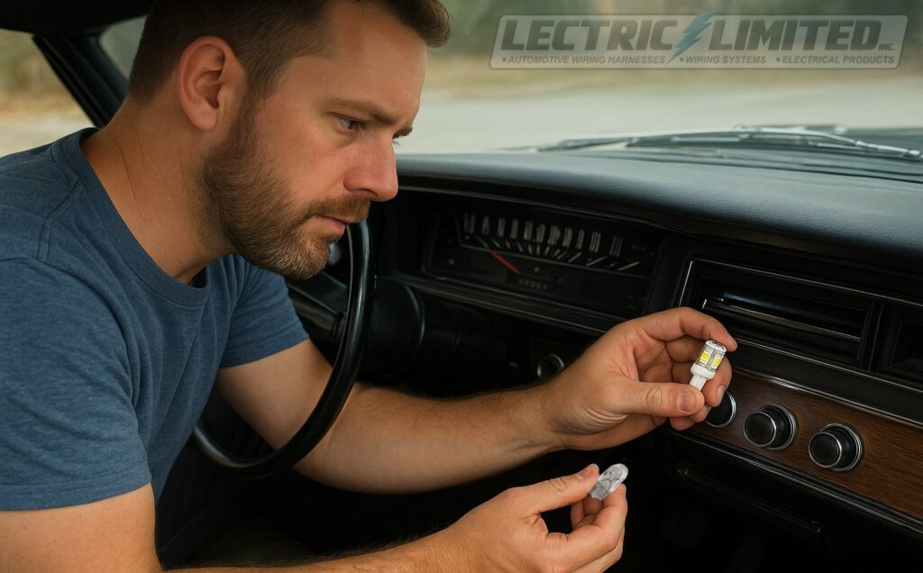
Yes …and no. LED bulbs require special attention. You can replace most original incandescent bulbs with modern LED bulbs to improve brightness, reduce heat, and lower current draw; however, it is important to note that LEDs operate differently from incandescent bulbs.
Because LEDs are electronic components (light emitting diodes) rather than filament-based bulbs, they are not compatible with the variable-resistance style dimmer used in classic-car headlight switches. As a result, while LEDs will function properly in locations such as the dash, gauge cluster, and dome light, they will not dim or fade smoothly when the headlight dimmer knob is rotated. Instead, they typically remain at a constant brightness or turn on and off abruptly at the ends of the dimming range. This behavior is normal and not a defect in the LED bulb or vehicle wiring. Using a PWM (pulse width modulation) controller may be an option to allow your LEDs to brighten & dim. Also, LEDs often require an electronic “no load” flasher or proper load resistors to prevent hyper-flashing or non-operation of the turn signals and turn signal indicators on the dash.
Terminology (as it relates to wiring)
CORVETTE “C” GENERATIONS:
- C1: 1953-1962 Corvette. The “solid axle” or “straight axle” cars. Lectric Limited manufactures wiring for C1 Corvette.
- C2: 1963-1967 Corvette. The “mid-year” and Sting Ray years. Lectric Limited manufactures wiring for C2 Corvette.
- C3: 1968-1982 Corvette. Includes 1968 Shark, and 1969-76 Stingray years. Lectric Limited manufactures wiring for C3 Corvette.
- C4: 1984*-1996 Corvette. Completely redesigned with modern suspension and digital dash. Note: There were no 1983 production cars due to plant change-over from St. Louis, MO to Bowling Green, KY.
- C5: 1997-2004 Corvette. Introduced the LS1 engine and the hydroformed chassis.
- C6: 2005-2013 Corvette. Exposed headlights returned; Z06 and ZR1 performance milestones.
- C7: 2013-2019 Corvette. Aggressive design, advanced electronics, and the LT1/LT4 engines.
- C8: 2020 & up Corvette. First-ever mid-engine Corvette.
DATE CODE:
A date code in relation to cars from the 1950s to 1980s typically refers to a series of alphanumeric characters stamped or printed on various parts of the vehicle that indicate the date of manufacture for that specific component. This could be found on items like the engine, transmission, tires, glass, or other major parts of the car. These codes help determine when the part was produced, which can be useful for identifying the original equipment in a car, verifying its authenticity, dating its components or for manufacture’s quality control purposes.
As date codes relate to wiring, most of the time the wiring itself was not date coded. However, spark plug wires were. Spark plug wire date codes on cars from the 1950s to the 1980s were used to indicate the manufacturing date of the wires. These codes were primarily stamped onto the wire itself. Spark plug wire date codes are similar in purpose to those found on other parts of the vehicle: they help identify when a specific set of wires was made, which can be important for determining the authenticity and originality of the car’s components, particularly for classic car restoration. Lectric Limited manufactures date-coded spark plug wire sets for G.M., Chrysler and AMC vehicles.
NOS PART:
An NOS car part stands for “New Old Stock.” This refers to automotive parts that were manufactured at the time the car was produced, but have never been used, installed, or sold. These parts were typically made and stored in warehouses or by the manufacturer for future use, but they were never installed on vehicles or sold to customers at the time.
Key Characteristics of NOS Parts:
- New & Unused: NOS parts are new, meaning they have never been installed or used on a car, but they are old in terms of their production date. However, it’s important to consider that certain materials, like rubber, plastic, wire insulation, even headlight bulbs can degrade over time, even if the part has never been used.
- Original OEM Parts: NOS parts are usually OEM (Original Equipment Manufacturer) parts, meaning they were produced by the original manufacturer of the vehicle or a licensed supplier during the vehicle’s production run.
Considerations When Using NOS Parts:
- Aging: Even though NOS parts are new and unused, they are old. Some materials (like rubber seals, gaskets, wire insulation, hoses) may degrade over time due to age, even if the part has never been installed.
- Availability: NOS parts can be difficult to find, especially for rare or older models. They often come at a premium price due to their rarity.
- Authenticity: Not all “NOS” parts are truly new old stock. Some parts may be described as NOS when they are actually just old but used parts. It’s important to verify the part’s condition and place of origin when purchasing.
OEM PART:
An OEM car part stands for Original Equipment Manufacturer part. These are parts that are made by the same manufacturer that supplied the original components for the car when it was first built. In other words, OEM parts are identical to the parts that were originally installed in the vehicle during its production, as they come from the same source, meet the same specifications, and are designed to fit and function just like the original parts.
Key Characteristics of OEM Parts:
- Manufacturer’s Source: OEM parts are produced by the car’s manufacturer (or a supplier working on behalf of the manufacturer), and they are the same parts that were used to assemble the vehicle at the factory. For example, if you drive a Toyota, an OEM part would be a part made by Toyota or a designated Toyota supplier.
- Factory Quality: OEM parts meet the same quality standards and specifications as the original parts that were installed in the car when it was new. They are built to fit perfectly and function as intended in your vehicle.
- Vehicle Compatibility: Because they are made by the vehicle manufacturer or their approved supplier, OEM parts are guaranteed to fit and be compatible with your car’s make, model, and year.
Why Choose OEM Parts?
- Guaranteed Fit & Compatibility: Since OEM parts are made to the exact specifications of the original parts, they are guaranteed to fit your car properly and work just as the original part did. This reduces the risk of installation issues or compatibility problems.
- Quality & Durability: OEM parts typically meet the manufacturer’s quality standards, meaning they are made with high-quality materials and are designed to last. Using OEM parts can help ensure the continued reliability and safety of your vehicle.
REPRODUCTION PART:
A reproduction car part refers to a part that is newly manufactured to replicate an original part that was used in a vehicle at the time it was produced but is no longer made by the original manufacturer. These parts are typically created to match the exact look, fit, and functionality of the original part, making them suitable for restorations or repairs, particularly for classic or vintage cars where the original parts might be unavailable or hard to find.
Key Characteristics of Reproduction Car Parts:
- Reproduction parts are often made to exactly mimic the original parts in appearance, size, and function, but are manufactured by third-party companies that specialize in reproducing classic car components.
- They are not OEM (Original Equipment Manufacturer) parts because they are produced after the vehicle’s original production run and by companies other than the original manufacturer.
- The materials used for reproduction parts are often similar to those used in the original parts (e.g., steel, rubber, chrome, glass). However, advances in manufacturing processes sometimes allow for improved materials that can offer better durability or enhanced performance over the original.
REPLACEMENT / AFTERMARKET PART:
- These are parts typically made by third-party manufacturers that are designed to fit and function like the original parts but may not be identical.
- Replacement/aftermarket parts can be more affordable than OEM parts and may offer different options in terms of performance, style, or features.
- While many aftermarket parts are designed to meet or exceed OEM standards, the quality can vary widely depending on the manufacturer.
ROADSTER:
1953 -1955 Corvettes were roadsters, they had side curtains (side glass windows), no roll up windows. NCRS considers a roadster the same as a convertible.
BIG BLOCK:
A big block car refers to a vehicle that is powered by a big block engine, typically a large-displacement V8 engine that is physically larger and heavier than smaller V8 engines (like the small block engines). Big block engines usually have a displacement greater than 400 cubic inches (ci). Chevrolet big block engines: 396, 454 and above. Chrysler (Mopar) big block engines: 426 Hemi & 440 Magnum.
SMALL BLOCK:
A small block car refers to a car that is powered by a small block engine—a type of V8 engine that is generally smaller in displacement and physical size compared to larger V8 engines, often referred to as big block engines. The term “small block” is most commonly associated with Chevrolet and its famous small block V8 engines. While other manufacturers also produced small block V8 engines, the Chevrolet small block is by far the most recognized.
Small block engines are typically V8 engines with a displacement of under 400 cubic inches. While the exact displacement can vary. The first small block V8 engine by Chevrolet was introduced in 1955 with the Chevrolet 265 cubic inch (ci) engine. Over the years, the small block has been offered in various displacements, including the 283, 302, 327, 350, 383, and 400 ci variants.
T-3 HEADLIGHTS:
A Guide T-3 headlight refers to a specific type of automotive headlight bulb that was produced by the Guide Lamp Company, which was a division of General Motors. The T-3 designation refers to a particular style and design of sealed beam headlight that was widely used in vehicles from 1940s to 1972.
The T-3 is a sealed beam headlight, meaning the entire bulb and lens assembly is a single, sealed unit. Unlike modern headlights, which have separate bulbs and lenses, sealed beams are designed as a single, durable unit that integrates the lens, reflector, and bulb.
The most distinct feature of the Guide T-3 headlight is the T-3 marking that appears on the lens of the headlight. The “T-3” designation is often embossed or molded into the glass lens and became a well-known symbol of quality and performance.
The “T” stands for “type” or “technology”, and the “3” was a specific model or version within Guide’s product line.
Lectric Limited manufactures some of these headlight bulbs. See our online catalog for your application. T-3 is a registered trademark of Lectric Limited.
Where can I get discount coupon codes for Lectric Limited products?
Check out…
- Follow us on Facebook for new products, tech tips, specials, and exclusive Discount / Coupon Codes!
- Go to our Specials page.
- “NCRS Driveline” Club Magazine – full page advertisement.
- “On the Road” Shows we attend.
Where Can I Buy Parts You Don’t Sell?
Where can I buy wiring for my pre-1953 vehicle?
Currently, we only offer wiring for the vehicles listed in our online catalog. For vehicles from the 1920s to 1950s, some of the wiring is being manufactured by Harnesses Unlimited, (610) 688-3998. Please note that Lectric Limited is not affiliated with this company.
Where can I buy electrical parts you don’t sell?
Our full range of electrical products—including wiring and repair components we manufacture, sell, or can source—is listed on our website. To view available items, see our online catalog.
If the part you’re looking for doesn’t appear, it means we do not manufacture it, cannot source it, and usually do not have any alternative suppliers to recommend. We appreciate your understanding.
That said, eBay can be a great resource for finding these types of products.